Proper wiring to avoid ground loops

GroupDIY Audio Forum

Help Support GroupDIY Audio Forum:

This site may earn a commission from merchant affiliate links, including eBay, Amazon, and others.
Related, but not terribly significant: In the 1970's one of the leading Hi-Fi magazines ran an article that said noise levels in home stereos could be reduced by plugging the central unit of the stereo (preamp in my case, receiver in others) into the AC power outlet then connecting each additional piece of your stereo gear to the preamp/receiver and measuring the voltage between the two chassis. You were then to flip the AC cord of the most recently connected piece of gear at its connection point - remember, these were two-prong days - and leave the AC cord in the position that produced the HIGHEST voltage between the two chassis. You would repeat this with each piece of gear (amp, turntable, CD player, cassette player, etc). Having ground pins on all our modern gear makes this very inconvenient (you could use three-to-two pin pigtail adapters), and I never heard a significant reduction in system hum or noise of my system, but I'm wondering if any of you actual electrical engineers can see even a hint of usefulness in this idea. I think it was either in Absolute Sound, or Stereophile. Your insights would be appreciated.
 
I am surely repeating myself but multiple ground noise contamination issues are lumped together and all called "ground loops", despite few actual loops but that is a starting point. This is ....

So true and cause of much misunderstanding beyond the audio sphere. In particular the role of the actual planet "Earth" causes much confusion. The usual terminology eg "Ground" doesn't help tbh 🙄
 
Depending on the ambition level an ultra isolation transformer could be used. Check the Bay, not expensive, other than the freight.
The US standards for AC line connected equipment would fail miserably in EU, where both pins in the socket are "hot",
and hum is a rare problem.
 
Related, but not terribly significant: In the 1970's one of the leading Hi-Fi magazines ran an article that said noise levels in home stereos could be reduced by plugging the central unit of the stereo (preamp in my case, receiver in others) into the AC power outlet then connecting each additional piece of your stereo gear to the preamp/receiver and measuring the voltage between the two chassis. You were then to flip the AC cord of the most recently connected piece of gear at its connection point - remember, these were two-prong days - and leave the AC cord in the position that produced the HIGHEST voltage between the two chassis. You would repeat this with each piece of gear (amp, turntable, CD player, cassette player, etc). Having ground pins on all our modern gear makes this very inconvenient (you could use three-to-two pin pigtail adapters), and I never heard a significant reduction in system hum or noise of my system, but I'm wondering if any of you actual electrical engineers can see even a hint of usefulness in this idea. I think it was either in Absolute Sound, or Stereophile. Your insights would be appreciated.
I vaguely recall hum issues decades ago while recording when using some budget consumer gear like VCRs with two wire line cords where the recorders internal audio signal ground tried grab a pseudo ground connection by capacitor coupling into line cord neutral. If the line cord connection was inadvertently reversed that capacitor connected to line instead of neutral and dumped 60 Hz current into the signal ground. Not enough to be dangerous but enough to cause noise.

Since back then, modern SKUs with two wire line cords use double insulated transformer primaries and polarized plugs. The wider blade in a polarized plug is the neutral (nominally 0V) contact. This 2 wire line cord polarity is far from guaranteed, so trust but verify.

JR
 
Related, but not terribly significant: In the 1970's one of the leading Hi-Fi magazines ran an article that said noise levels in home stereos could be reduced by plugging the central unit of the stereo (preamp in my case, receiver in others) into the AC power outlet then connecting each additional piece of your stereo gear to the preamp/receiver and measuring the voltage between the two chassis. You were then to flip the AC cord of the most recently connected piece of gear at its connection point - remember, these were two-prong days - and leave the AC cord in the position that produced the HIGHEST voltage between the two chassis. You would repeat this with each piece of gear (amp, turntable, CD player, cassette player, etc). Having ground pins on all our modern gear makes this very inconvenient (you could use three-to-two pin pigtail adapters), and I never heard a significant reduction in system hum or noise of my system, but I'm wondering if any of you actual electrical engineers can see even a hint of usefulness in this idea. I think it was either in Absolute Sound, or Stereophile. Your insights would be appreciated.
I believe this was based on a total misunderstanding that putting the system in its worst case situation and using brute force to kill the resulting differential voltages by connecting the various chassis via the cable shields would result in the best noise performance.
This method's advocates completely neglected the fact that cables have resistance and inductance and that connections are never perfect.
It is true that re-orienting plugs may yield better noise performance, though.
There's a lot of misconception in HiFi magazines (and blogs).
 
Depending on the ambition level an ultra isolation transformer could be used.
An iso xfmr proceeds on two levels.
Galvanic isolation, which effectively breaks ground loops between the power distro PE (Protective Earth) and another "earth", which may happen when interconnecting two distant sites, such as a remote van to a fixed studio, or a defective connection. This is what should cure hum and buzz.
Electrostatic (Faraday) shielding between primlary and secondary. Transients are dumped to earth and low-pass filtered by the leakage inductance of the xfmr. It pertains to clicks produced by switches.
The US standards for AC line connected equipment would fail miserably in EU, where both pins in the socket are "hot",
I don't get it. In my country and several others, I know for a fact that only one pin is hot. There may be some residual on the Neutral, but it's only a few volts at worst.
As I mentioned earlier, there were so-called "biphasé" distribution, where each leg was 110V, and 220V was available between two legs, but it doesn't exist anymore, for at least 40 years.
It's in the US that split-phase distribution has two hot legs.
BTW, I just figured out I had crossed my references in post #120.
"Diphasé" was two 110V legs 90° apart, resulting in about 155V between legs.
Most period multivoltage radios had a 155V tap in addition to the 110/125 and 220/240 taps.
 
Damn, you are right. Brown is phase, blue is neutral yel/grn protective ground. I was mistaken. However (most) EU plugs are not polarized, thus equipment power switches must break both wires, and same insulation requirements for both. Agency approvals and testing regimen are more severe, leading to more careful design and implementation of equipment.
 
The unique UK AC domestic power system, it runs from a breaker (or fuse) in a loop (ring circuit) between outlets, with one breaker, whereas in the US there are many breakers, a typical domestic breaker panel may have 20 slots.
The UK system includes an individual fuse in each very large plug for the outlets.
That would save the number of breakers.
The rest of the planet has not been wild at adopting the British Standard, maybe they think it is BS.
Using 100 or 117V, vs 220-240V, requires more copper in heavier gage wires. Insulation is less costly than copper.
The US system leaves partially inserted plugs exposing the pins, and the quality of outlets is not very high, springs losing their force is very common, outlets have to be checked and replaced.
Pins bend too easily and the typical soft brass alloy is not plated. Plugging in a 2kW room heater with a cheap single insulated non grounded extension cord can and does lead to house fires, as is not unheard of, usually from poorer districts.
If maintained well it is OK, but regulations and enforcement are weak.
The German, and north EU standard that I have seen looks much better than either above.
Once a standard is in place, it is extremely unlikely to ever change.
 
Last edited:
Due to differences in -neutral system- around the globe, no generalisation should be made about this topic and safety associated.
At my side, despite the -polarisation- of the main AC (EU and TT wiring), I always consider ALL wire HOT for my own safety when working on it...
AFAIK in my country there is no normative or mandatory for P and N connection at end plug, just convention, and only protective earth need mandatory marking.
Also, depending of neutral wiring system, distance to the local power distribution, and the 3 phase balance in the area, the neutral can deviate from 0V.

Cheers
Zam
 
Related, but not terribly significant: In the 1970's one of the leading Hi-Fi magazines ran an article that said noise levels in home stereos could be reduced by plugging the central unit of the stereo (preamp in my case, receiver in others) into the AC power outlet then connecting each additional piece of your stereo gear to the preamp/receiver and measuring the voltage between the two chassis. You were then to flip the AC cord of the most recently connected piece of gear at its connection point - remember, these were two-prong days - and leave the AC cord in the position that produced the HIGHEST voltage between the two chassis. You would repeat this with each piece of gear (amp, turntable, CD player, cassette player, etc). Having ground pins on all our modern gear makes this very inconvenient (you could use three-to-two pin pigtail adapters), and I never heard a significant reduction in system hum or noise of my system, but I'm wondering if any of you actual electrical engineers can see even a hint of usefulness in this idea. I think it was either in Absolute Sound, or Stereophile. Your insights would be appreciated.
Interesting story. Do you remember if that voltage should have been measured before or after connecting the interconnect cable? I have some dubious theory that would explain why such a procedure would make sense, but only if it is measured without the interconnect cable connected.

Often, amplifiers from that era, especially Japanese ones, had connectors for connecting the power supply for a preamp, tuner, turntable or timer (in times when you wanted your favorite radio station to wake you up in the morning).
 
You were then to flip the AC cord of the most recently connected piece of gear at its connection point...and leave the AC cord in the position that produced the HIGHEST voltage between the two chassis.

Do you have a reference to that article? That sounds backwards, typically you would flip the cords to the position which resulted in the lowest inter-chassis voltage, since you want the lowest possible common mode voltage between components since unbalanced interfaces have no common-mode rejection capability. My suspicion is that either you have remembered the conclusion of the article incorrectly, or the article author was very ignorant and tried to repeat something heard elsewhere and repeated the information incorrectly.
 
The unique UK AC domestic power system, it runs from a breaker (or fuse) in a loop (ring circuit) between outlets, with one breaker,

For completeness - whilst the loop / ring configuration is dominant in UK residential electrical installations, a radial configuration may be used in whole or part. And there is a current of thinking (see what I did there :) ) amongst some electricians that radial is often preferable now. Where used it uses the same fused plugs with MCB/RCD/RCBO protection at the consumer unit.
 
For completeness - whilst the loop / ring configuration is dominant in UK residential electrical installations, a radial configuration may be used in whole or part. And there is a current of thinking (see what I did there :) ) amongst some electricians that radial is often preferable now. Where used it uses the same fused plugs with MCB/RCD/RCBO protection at the consumer unit.
I am a big fan of GFCI outlets and have installed several to replace my ungrounded outlets.

JR
 
Here, outlets with GFCI are unavailable and mostly unknown.
GFCI's are at the distro panel and mandatory (at least two).
All circuits are protected by standard circuit breakers.
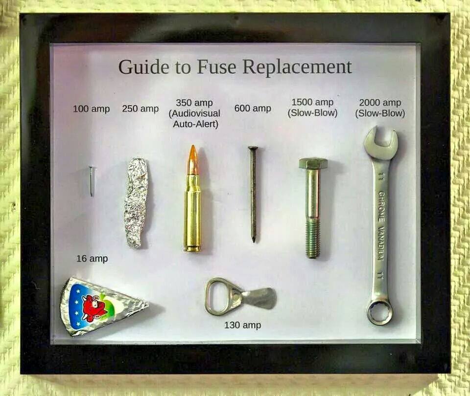
I guess if we had fuses in the plugs, most of them would end up being replaced with copper wire or a nail. :)
 
I guess if we had fuses in the plugs, most of them would end up being replaced with copper wire or a nail.
HjqfZZh.jpeg
 
Do you have a reference to that article? That sounds backwards, typically you would flip the cords to the position which resulted in the lowest inter-chassis voltage, since you want the lowest possible common mode voltage between components since unbalanced interfaces have no common-mode rejection capability. My suspicion is that either you have remembered the conclusion of the article incorrectly, or the article author was very ignorant and tried to repeat something heard elsewhere and repeated the information incorrectly.
Before the days of polarized cords, they would install a Y capacitor from AC common to chassis. Unfortunately, back then that capacitor didn't have the regulatory standards it has to pass to be used there in the circuit and they would short out over time and then it was a 50/50 chance the user got shocked plugging it in. Guitar players called it the "deathcap". Which I find it being nonsense because they don't understand the industry's mistake on that part. Now its not an issue because you have to use a cap that is specifically designed to go there and its designed to open instead of short.
 
Back
Top