RCA Ba2A Pre amp qestions & answers

GroupDIY Audio Forum

Help Support GroupDIY Audio Forum:

This site may earn a commission from merchant affiliate links, including eBay, Amazon, and others.
I went out of the BA2 into the 600 side of the edcor, then out the 15k and ran it through RMAA... 


but without as much gain loss.

If I'm reading you right then you should be having no gain loss - just the opposite - 600:15K is about + 14db of gain . . .


how does the math work?


turn ratio = sq root of impedance ratio


and without the transformer/load resistor going straight into the soundcard, it sounds real thin and honky... ie: not right....


Soundcard input impedance is something high, say 10K.  With a 600r resistor on the sec, the primary is presenting a 15K load on the tube.  With a 10K load on the sec . . .


The 15K:600 I have in front of me now says that with the sec loaded with  600r, I get a primary impedance of 18K at 1KHz and 13K at 120Hz.  Not perfect, but close enough to give near constant impedance on the primary.


Now, when I load that same transformer with 10K I get a 95K reflected load at 1KHz on the primary, But at 120Hz the load has dropped to only 4.6K.  That's a 20X difference.


I have another 15K:600 transformer that will measure a 17K pri load with a 600r sec load at 1KHz and will measure 17K at the pri with a 600r sec load at 120Hz.  Pretty much spot on.

When I load the 2nd transformer sec with a 10K load I get a pri impedance of 214K at 1KHz,  and 78K at 120Hz.  That's only 2.7 times difference.

If I had to pick which transformer might sound more toppy when misloaded, I'd guess the first one.

Transformer No 2 has a primary inductance that is nearly six times higher than No 1.

Doug has mentioned that his stock BA2s aren't fussy about what resistance the sec is loaded with.  You can see from his plots that the stock BA2 extends to a lower corner frequency than A-25/BA2.

My A-25 BA2s change some without termination but I haven't tried them on a lot of different Hi Z inputs.  But your description sounds typical of what can happen in some situations without termination.  Try something higher, like 1K, 1.5K, etc and see if you can reach a happy medium of overall gain loss and tonal balance/distortion. 


*DING!* The penny just dropped... i think...  I read and read that last post and couldn't quite understand it. I googled and read some docs about transformers from Jensen... and I think I got it... but please correct me if i'm wrong...

The impedance designations given on a transformer AREN'T the actual impedance... ie: the transformer isn't generating impedance, it's merely reflecting the impedance of the mic/amp. I have been hung up on the numbers, thinking they were the actual impedance and therefore have been very confused...

Going back to Dougs post on the cinemag...

Having the cinemag wired for "150ohm : 50K", which is an impedance ratio of 1 : 333, a 150ohm mic plugged in would reflect a 50K load on the first tube.

Having the cinemag wired for "600ohm : 50k" which is an impedance ratio of 1 : 83, a 150Ohm mic would reflect a 12K load on the first tube.

In either scenario, a load resistor on the secondary could be adjusted to reflect the same impedance to the mic:

Wired 150:50K, a 360K resistor would reflect around a 1k load to the mic.

Wired  600:50K, an 80K resistor would reflect around a1K load to the mic.

SO logically, the next thought is, what is the optimal impedance that the first tube in the circuit wants to see? And I'm going to guess it's 50K as per Dougs reccomendation... my tube theory isn't deep enough to figure it out for myself yet... out of curiosty, what impedance does the first tube reflect to the mic without any resistor in place?

Thanks for the tutelage... I sure hope I'm right on this transformer stuff... coz it was a bit of an awakening....
 
It's not about the tube, it's about the mic, and the optimal transformer conditions considering all factors.  Original ba2 input designed for unloaded sec, Cinemag not. 
 
out of curiosty, what impedance does the first tube reflect to the mic without any resistor in place?

This is an excellent question and one that does not have a lot of printed data of exact numbers for reference.  For amps like a BA2 and others with an input transformer working into an open grid we usually assume that it's at least 1.5K or higher through most of the audio band.  The grid circuit acts like a very, very high impedance.

Remember that since you're dealing with an inductance, you have to ask - "what impedance at what frequency" because the impedance changes with frequency, which is what those measurements in the previous post were showing.
 
So I want to hook up a VU to my BA2... on the schem it's got taps off both V1 and V2 cathode resistors going to a switch i assume, then off to a meter... is this where I'd hook up the VU meter too? and if so, whats the deal with the switch for V1 cathode and V2 cathode?

Thanks!
 
that's for measuring cathode current.  VU would connect to audio output, through the correct resistor network. 
 
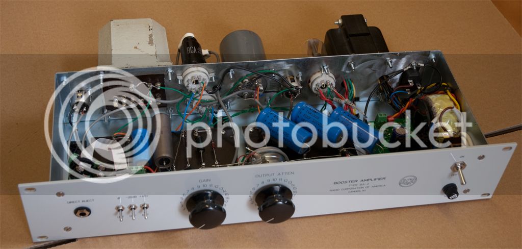
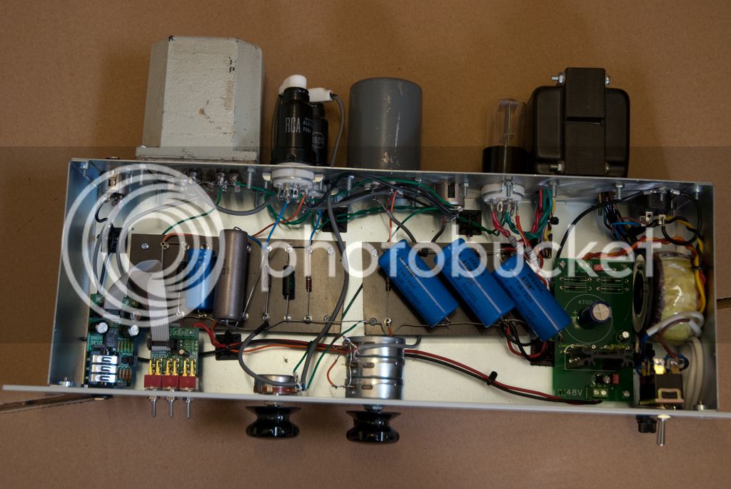
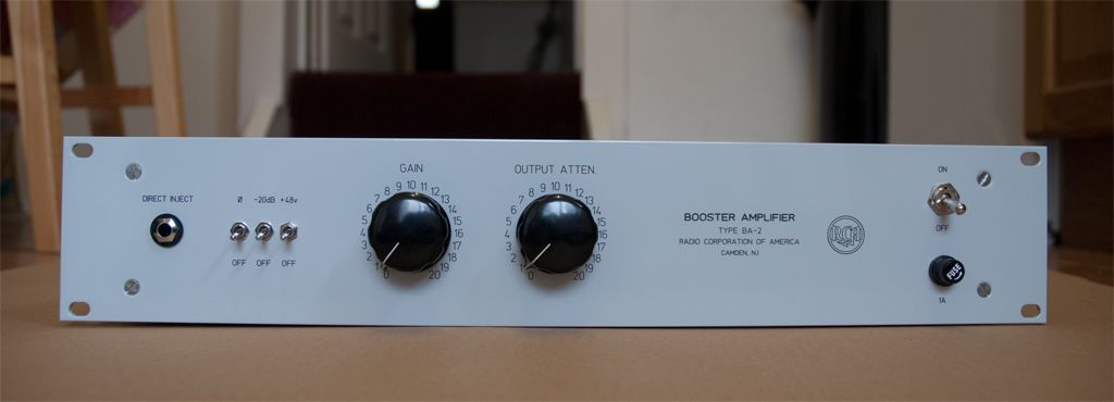
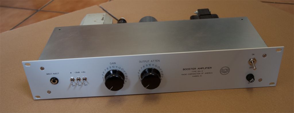
I FINALLY got the front panel powder coated and engraved.  Below is the obligatory porn:

BA-2-front.jpg


BA-2-front2.jpg


BA-2-front-top-of.jpg


BA-2-above.jpg


BA-2-above-2.jpg


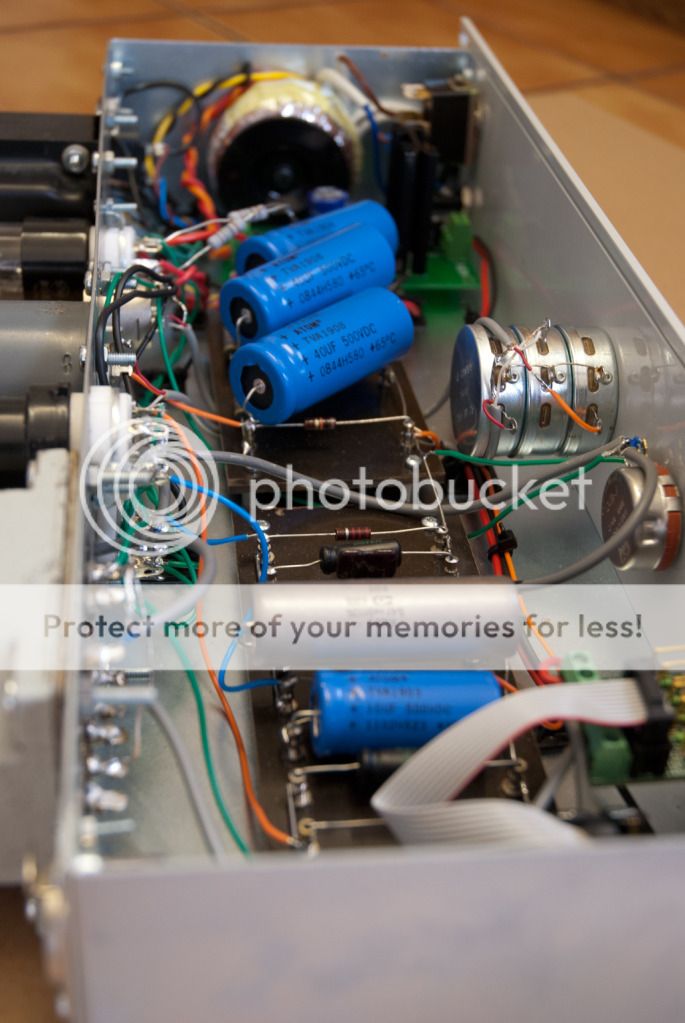
If you look closely at the back, you can see the green heaters wires twisted together.  Do they look twisted tight enough?
 
Looks fantastic.  Wires twisted enough if you're happy with hum level; can't answer that. 
 
Thanks Doug!

I've just finished spraying the BA-6A transformers I bought from you -they're looking good as new now!  Can't wait to get cracking on that one.
 
emrr said:
C1 and C3 are cathode bypass, and 25V rating is more than plenty. 

C7 is power filter.

C2 is already overkill large.  Nothing to change there.  Nornal to see 0.1 or 0.25 in that impedance scenario.

R1-R2 affect bias point, and will make your distortion point move if you are into running up into distortion with test equipment and fiddling with values for most headroom.  They picked that spot for a reason; you may find you have a different reason to pick a different spot.  At normal operating levels (with plenty of headroom) you may not hear any difference between any reasonable chosen point.  Not uncommon to see 2.2K or 2.7K biasing that tube in triode in low level preamp stages.

As a general statement, it's not uncommon to find that two stage preamps of this vintage have essentially the same overload point in each stage, meaning there's great headroom in the 1st and nowhere left to go in the 2nd if the 1st is going full blast already.

Now I see why you said to go here. Thanks.
 
If we're lucky Cinemag may have a good SE OT for this project at some point.  They already have a 7:1 that was kind of made for one of the UA console pres that should work ok for BA2.  Apparently David is working on a new design.

A-25 has pretty much already made it into "AY(F)KM" market price territory.  Lundahl may even be less $ now.
 
I think that C2 should be carbon film, right? I think something like a nice WIMA cap would do. I have a polarized JJ brand 47uF electrolytic cap rated at 500v, but if I think electro might be wrong for this application.
 
47uf would be very big also. The schematic says 0.5 uf. I used a 0.47uf Mallory 150, which is a film cap. Wima would also be a film cap.
Film caps are not 'carbon' film, they are different kinds of plastics. Check out the different film for MKS vs MKP Wima via google.
 
I used a Russian PIO for C2.  I can't remember where I read they used PIO caps in that position, it might have been this thread (or I could have imagined it).

EDIT: It was this thread:

emrr said:
The metal cased caps are paper/oil types, and the 0.047 and 0.1 types probably are also.  I've never been entirely sure about that type, but cap info in RDH4 suggests it as a primary manufacturing method.

On exact values, older types are usually +100%/-10% versus new types which seem to be +/-10 or 20%.  Older types are seldom low, and frequently much higher than specified, 100% high not being abnormal in an original cap.  New types seem to always be slightly low to dead on, seldom higher than quoted.  Sometimes you have to take this into account in restorations, and buy higher than quoted to match what you are actually replacing.  This of course takes some intelligent 'reading between the lines' on the original design.  It's not at all uncommon to recap an old piece and have less low end that you had before the cap job, simply because you went by the book.

EDIT NO 2: There's some good cap info on page 1 of this thread from emrr.  You can lower the capacitance of C2 apparently.
 
A Russian PIO eh?

I just ordered a pair of wima 400v 0.47uF film caps, and a 400v ceramic disc cap for C8.

If I make R11 variable, I wonder how it would effect things. I have to read up on the tilt option.
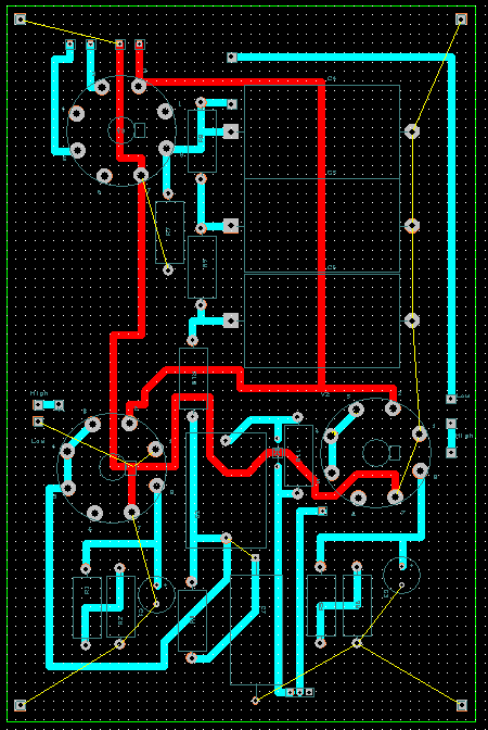
My first dual layer high voltage PCB attempt. I'm going to look it over tomorrow and hopefully etch it. Most yellow traces are symbolizing ground connections, if they are not supposed to be there they will be removed.
CaptureBA-2A.png

 
Back
Top