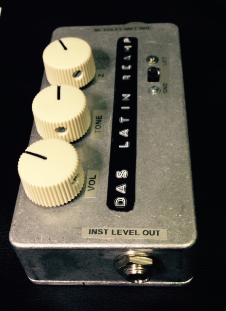
Reamp Box with Neutrik 10/3 transformer

GroupDIY Audio Forum

Help Support GroupDIY Audio Forum:

This site may earn a commission from merchant affiliate links, including eBay, Amazon, and others.

Whoops

Well-known member
GDIY Supporter
Joined
May 9, 2008
Messages
8,424
Location
Portugal
Hello,
I was in need for some Reamp boxes so after some research I found an article from an old magazine with a reamp circuit using the small and inexpensive Neutrik transformer model 10/3.

5t1k8Zy.png


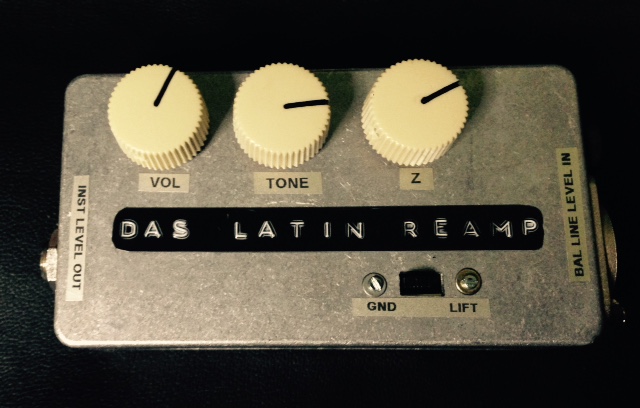
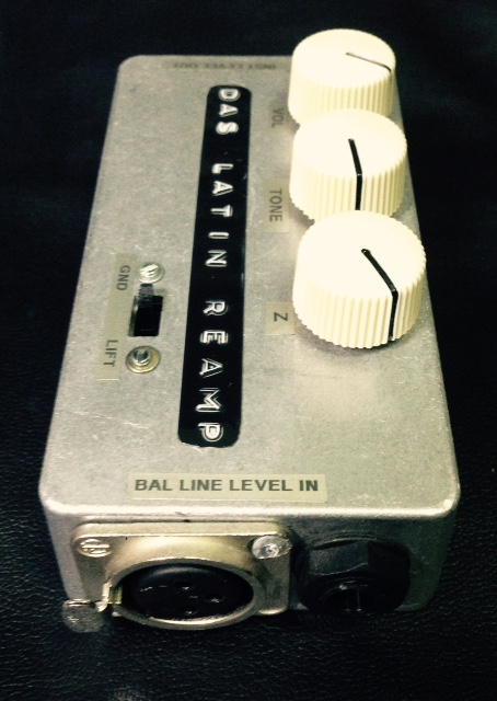
The circuit is simple to do (did it point to point) and the Impedance pot and Tone pots are really useful.
It's a cool and useful box.
aE4jVHo.jpg


BhVy9KB.jpg


wboOc9Z.jpg


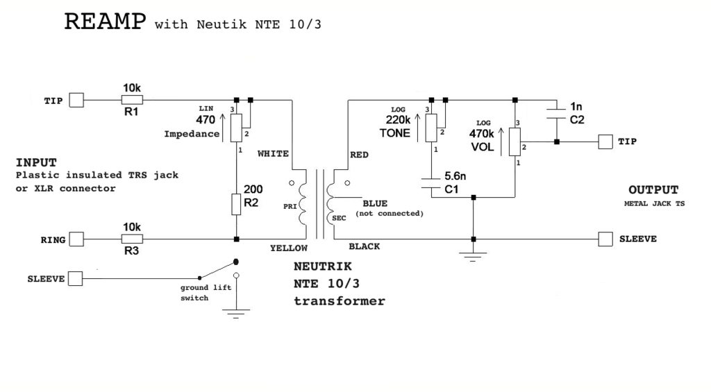
here is the schematic in case anyone want to try the circuit out:
ye6kmfyh.png
 

Attachments

  • Screen Shot 2020-09-09 at 01.36.33.png
    Screen Shot 2020-09-09 at 01.36.33.png
    106.2 KB
Thanks heaps for this. I saw & commented on your previous post but was wondering whether I have got this right from your schematic?
Couple of questions is the 470 impedance pot - OHM?
The 200 resistor i also assume OHM?
I think the rest of the layout i have correct although unsure about the ground lift wiring to the switch?
 

Attachments

  • Screenshot 2024-08-01 at 1.55.20 pm.png
    Screenshot 2024-08-01 at 1.55.20 pm.png
    191 KB
Hi Dave,

Usualy, in a schematic, if no multiplier is written, then the resistance value is in Ohms. Sometimes the designer will use the letter 'R' for the same purpose. So for a resistor or a pot, '200' or '200R' mean 200 Ohms.

Regarding the ground lift issue, it seems to me that your diagram shows 'chassis' and pin1 from the input both connected together at the same pin of the switch. The purpose of the switch is to disconnect the shield from the sound card and the amp chassis to avoid ground loops if needed.

So you have to have either input pin1 or chassis wired to the common pin of the switch and the other wired to any of the other pins. (If using a SPDT switch, as shown in you diagram).

Hope this helps,

Thomas
Thank you that does make sense. I always struggle when it comes to understanding switches (and as a result how to wire them!)
 
Back
Top