REDD EQ, Helios 69 and Dick Swettenham

GroupDIY Audio Forum

Help Support GroupDIY Audio Forum:

This site may earn a commission from merchant affiliate links, including eBay, Amazon, and others.
Winston O'Boogie said:
Hey, glad you got it sorted Erik, nice one.
Easy mistake to make.  I haven't turned on a piece of gear I made yet that failed to amaze me when audio comes out the other end.
Down some wires. 
Cool 👍

It really does sound so much better when you make it yourself!  ;)
 
Ian,
You wrote in post 285, "Hooking up the Helios EQ PCB is quite simple. Your input goes (via a 10K:10K transformer) to the pad labelled IN "
I thought it required a low I/P driving Z, such as 600 ohms?
 
Sorr said:
Ian,
You wrote in post 285, "Hooking up the Helios EQ PCB is quite simple. Your input goes (via a 10K:10K transformer) to the pad labelled IN "
I thought it required a low I/P driving Z, such as 600 ohms?

Transformers do what it says on the tin - they transform. The input impedance of the EQ is about 10K so I recommend a 10K:10K transformer to successfully reflect this input impedance to its primary. It looks like a regular line input to the outside world. The EQ is designed to work from a source impedance of no more than 2500 ohms. This is so it can be used directly after a 10K fader in a mixer. If you drive it from a low impedance source you can add a series resistor (there's a place on the PCB for this) to raise the soirce impedance to 2500 ohms. You don't have to do this though - if you drive from a low impedance source without the extra resistor, all that happens is the maximum boost and cut is increased by about a dB.

Bottom line is for a bakanced input you need a 10K:10K transformer but you can drive it from a low impedance source.

Cheers

Ian
 
I'm looking forward to  building a couple of your Helios EQs - thanks again for making them open source.

I think you've answered this above, but just to confirm - I have some 600:600 input transformers lying about. I know the circuit is designed with a 10k:10k in mind, but if I read your above post correctly, I can use a 600:600 but the maximum boost and cut is increased by a dB. Is that correct?

My other question is that I would like to use the 2128 amp circuit for make-up gain that was used in the original desks for the same purpose. Would the 2128 amp work with your circuit?

Here's a link to a doc with the 2128 in: https://groupdiy.com/index.php?topic=58393.msg948059#msg948059
 
letterbeacon said:
I'm looking forward to  building a couple of your Helios EQs - thanks again for making them open source.

I think you've answered this above, but just to confirm - I have some 600:600 input transformers lying about. I know the circuit is designed with a 10k:10k in mind, but if I read your above post correctly, I can use a 600:600 but the maximum boost and cut is increased by a dB. Is that correct?

My other question is that I would like to use the 2128 amp circuit for make-up gain that was used in the original desks for the same purpose. Would the 2128 amp work with your circuit?

Here's a link to a doc with the 2128 in: https://groupdiy.com/index.php?topic=58393.msg948059#msg948059

Yes, a 600:600 input transformer will be fine. Its lower source impedance may give you an extra dB of boost. Cut should be relatively unaffected.

The 2128 amp is perfect for gain make up.

Cheers

Ian
 
I've read through the posts here several times and still don't believe I have the entire picture if I go the helios line amp for makup gain.

Would it be 2128 straight to a 600:600 transformer? (I see this is already a no after more reading elsewhere)
or 2128 to 22113 to 600:600 transformer?
Or just 22113 to 600:600 transformer will provide enough makeup gain?

Also on the 2128 I don't understand what the FB "output" is exactly. Is it just a resistor to ground and the value sets the gain?
Looks to be so, and also could be replaced with a trimmer as well as R8 on the 22113 could be a trimmer to set gain?

As an experiment, I'm attempting to build the RS127 portion of the schematic on turret board/point to point.

Still waiting on the Carnhill inductor and a 10k:10k input transformer in the mail.

I'm thinking of keeping it passive, going balanced in, then straight out to di on a 1073 clone for now, but if I used an external PSU, I could have makeup gain.

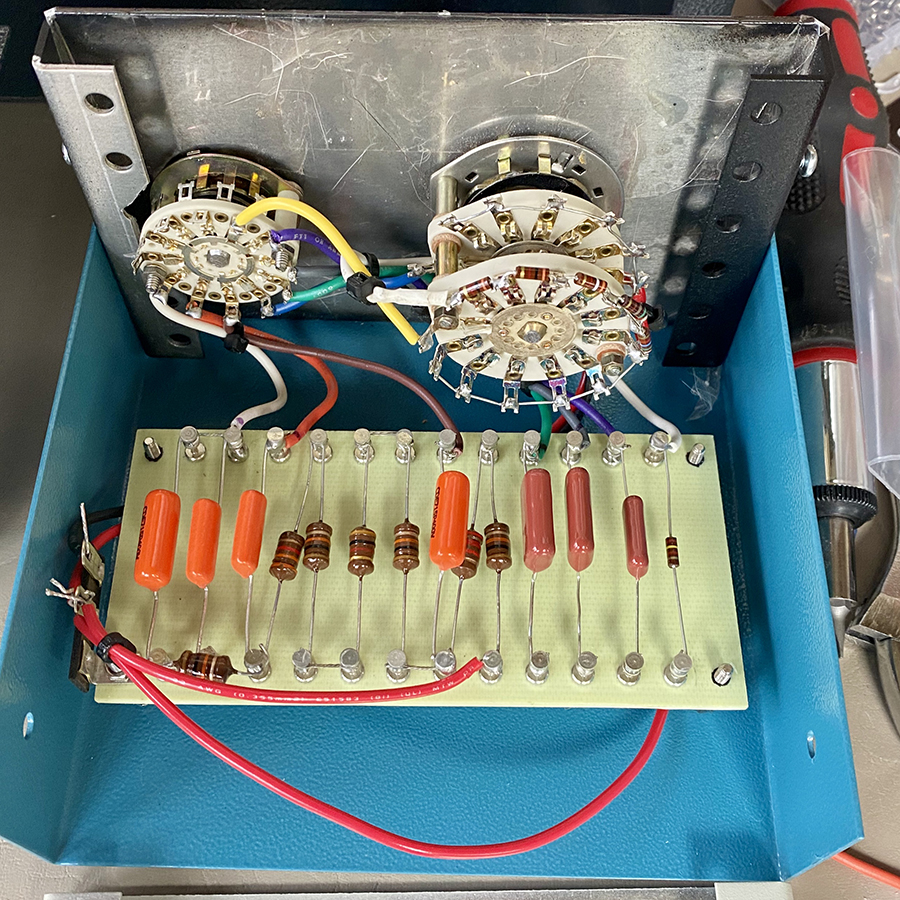
I'm housing it in a small 6x4" hammond case similar in size to the original. Resistors are soldered directly onto the switch. Caps and inductors are the only things on the turret board and the carnhill inductor will be mounted to the case with standoffs. Transformer will be rear mounted.

Here's a pic of my progress so far while I'm waiting on parts!

imHf9s4.jpg
 
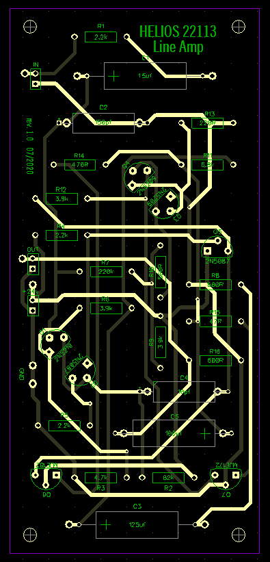
The 22113 is the main line driving amplifier. Because the rail voltage is only 24V, if you use a 600:600 transformer the maximum output level will be around +18dBu. Id you need more output level you could use a 150:600 transformer which will get you up to +24dBu.

The feedback pin connects to analogue 0V via a resistor and sets the gain of the amplifier. The 22113 has more than enough gain capability for EQ gain make up all by itself.

Not sure what the 2120 is. Do you mean 2128? The 2128 also has enough gain to make up for the EQ but it does not have the drive capability of the 22113. it is OK for use internally in a mixer where it only has to drive a couple of 10K pots or so but it is not really beefy enough to drive a 600 ohm load.

Cheers

ian
 
Perfect, exactly what I was looking for! Thank you! Yes 2128 was what I meant, corrected the typo :)

For a single 22113, does anyone see an issue using a quality wallwart with DC 24v, or do you think building a dedicated power supply is necessary?

I designed a PCB in the same form factor as the turret board that could sandwich under it, though I might replace R8 with a trimpot to set the gain.

dIAqsoN.png

 
I would definitely use a 24 turn trimpot. The loss in every passive EQ is slightly different.

I think your board layout could be improved. The 0V wanders around and passes through several vias on its way. You might like to think about making one side of the board  a 0V plane.

Cheers

Ian
 
Thanks for all your help!

Yeah, that board was a lazy auto-routed rough draft, lol
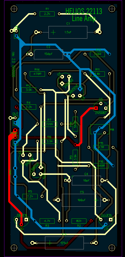
Here's an improved one, though maybe still not my final, I don't like having vias at all if I can help it, it's never caused me trouble, but it just bothers me for some reason. On this one 24v and 0v are much better and there's a ground plane on the bottom.

I'm by no means an expert at designing PCBs, just have done a handful for my hobby, mainly modular synth modules. All have been successful so far but I'm still learning and I'm sure I'm still making mistakes, I do know my early designs were terrible messes!
we1NisR.png


Edit:
oh yeah, here's my redrawn schematic, I've double checked for errors and don't see anything but it's always good to have a second or third pair of eyes to verify!
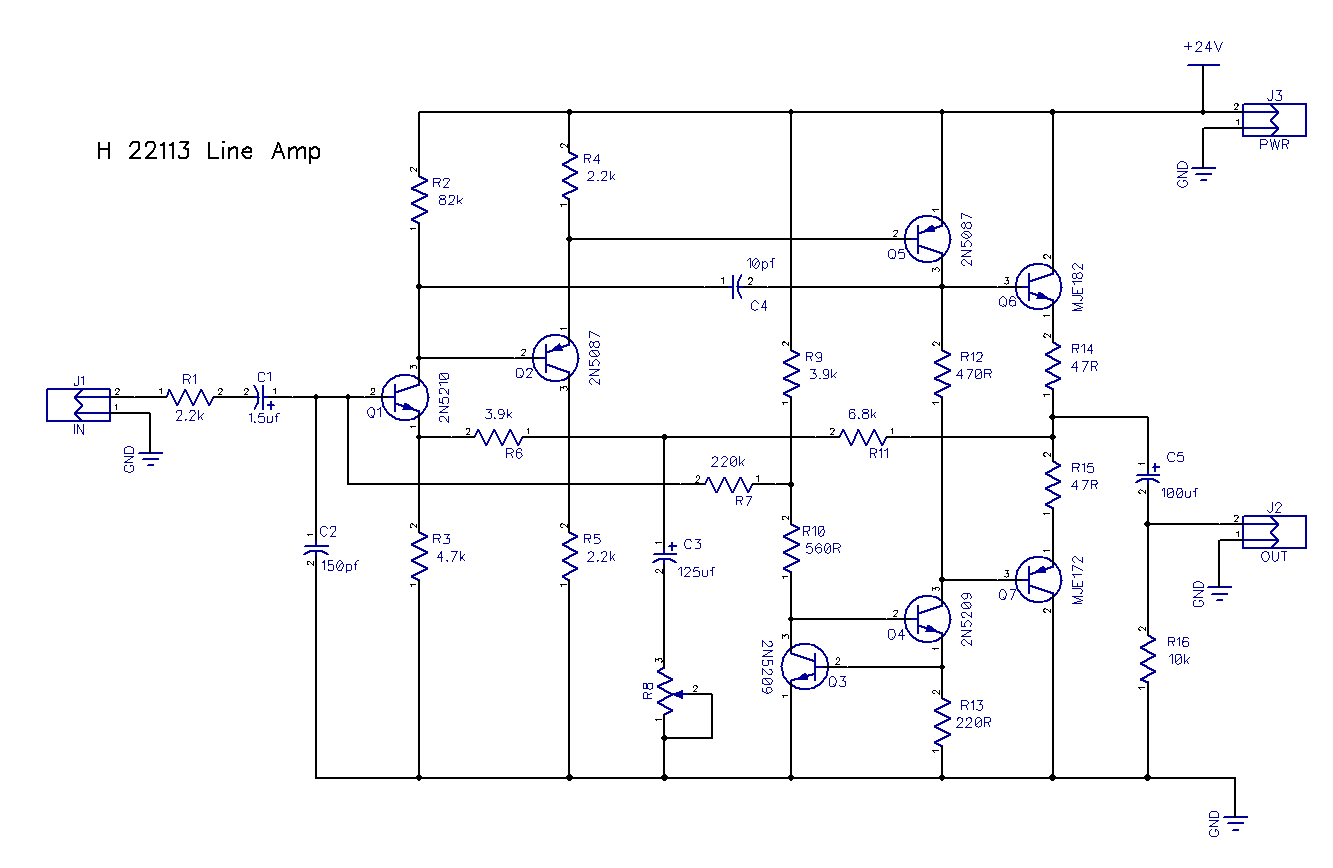
Edit: Updated with some corrections, I found a few errors as well as the error Ian pointed out below
mhCA3Ih.png
 
Layout is now much better. Schematic looks basically OK to me. Only error is R16 which should not be 600 ohms. It is just there to provide a dc path so the output cap can charge up. 10K will be fine.

Cheers

Ian
 
Thank you so much for your help!

Once I get the rest of the parts in to finish it, I'll post how it went and some final photos and the wiring guide if anyone is interested. If I do add the on board makeup gain and power, then I will say it's a tad more effort and cost to build than a single band EQ probably deserves, and next time I'll likely go for the full EQ that you designed.

Either way, I think it will be pretty cool to have one standalone RS127 in my home studio.
 
Excellent. Another group member, Pierre Petit, hosts an independent gallery of DIY projects based on my designs. If it is OK with you I will forward the pics you post to him for inclusion in his gallery.

Cheers

Ian
 
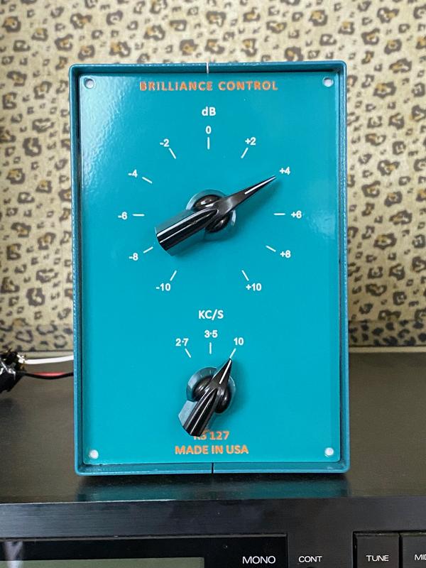
I've got it mostly finished! It's working currently with no transformers and sounds great. I'm going out of my MOTU and going into the DI of a 1073 clone.

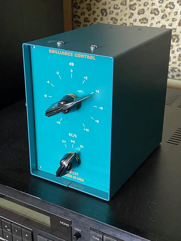
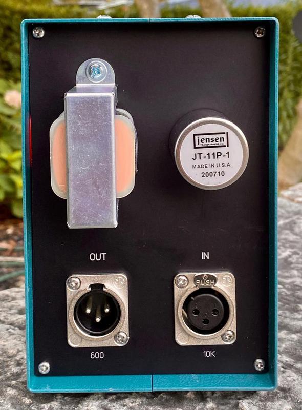
I got the panels in today and fitted the front panel, I have to dremel out some holes in the rear to fit the rear panel for transformer mounting and the xlr. edit - I have completed the rear panel as well. I still haven't actually connected the input transformer, or the line amp/output transformer as I'm awaiting PCB's from china. I'll do the input transformer tonight or tomorrow though.

gxi7alv.jpg
 
Q9ZOlLY.jpg
 
SAaFP3Z.jpg

The case and panels slightly clash with different shades of blue, so if it bothers me too much I may order the black version of the case and use this blue one for something else. Black sides with a turquoise front would look pretty good.

One thing I noticed that's awesome, at least with the way it's connected currently, is it's dead quiet. With signal going through it, turning up the db to +10 at any frequency, there's no perceivable hiss even with headphones on. I have a helios type amp PCB on order, just waiting on those PCB's and parts.
 
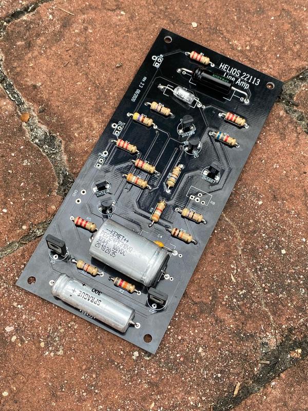
I received the 22113 amp PCBs today and put one together. Works great in the RS127 build! No need for an external amplifier now :)

I used a mean well external 24v wall wart type transformer (picked it as it's the same line as the Heritage Audio HA-73EQ uses) It's a cheap switching psu but it seems good and is noiseless. I used a 600:600 output transformer as it's what I had on hand and I don't have any headroom issues that I can tell with the limited testing I've done so far.

I also opted for a panel mount trimmer since I had a few laying around (the PEC screw ones, the style like on an LA2A) That will make matching a pair easier especially as the amp pcb is pretty difficult to get to.

qr3J835.jpg


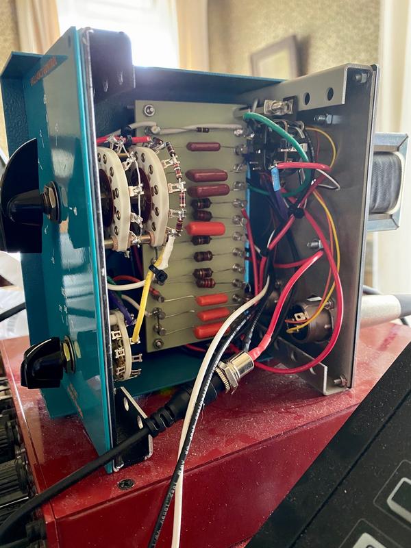
Here's the guts, the amp card is sandwiched under the turret board. I just have to clean up the wiring a bit, drill the holes for the power entry and the volume trimmer and it will be done.

EeIG3Hm.jpg
 
Certainly you can publish them. If you want to wait until tomorrow, I have it completely finished now, but it's dark so I can't get a good final pic until daylight.

Thank you for making the original design! This was fun to do, it's always great when it works right off.
I'll probably make a couple more of these as well as a stereo redd eq. I have a stack of the helios line amp pcbs now. :)

I did some comparisons with the software and it is spot on with the curves! I also can't get it to distort, my MOTU interface distorts before this does, so it has plenty of headroom.

ruffrecords said:
Cool project. If its OK with you I will forward the pics to Pierre for inclusion in the gallery.

Cheers

Ian
 
Hi Ian, I’m building a classic duo with Helios 69.  I’m not really too bothered by the insertion loss so I might just forge ahead, but I’ve got some 2520s laying around so considering a make up gain stage utilising those... I realise I'd have to supply power somehow.  I’m pretty new when it comes to design... would it be feasible to adapt the make up gain circuit you have for the TL072 for a discrete op amp?

Or maybe something like the 2nd stage of this CAPI board could work? (Maybe even one board for both channels if I can trim the gain of the 2nd stage to match the first)
https://capi-gear.com/catalog/product_info.php?products_id=438

Also, not sure if it would matter, but should the gain make up stage go before or after the 2nd tube stage?

I ordered a batch of 10 Helios 69 boards so if anybody needs any let me know!
 
The Classic design usually achieves 70dB overall gain which is more than enough for most purposes. The insertion loss for a Helios 69 EQ is about 14dB so you would still have  56dB of gain without a separate gain make up amp. This will be enough for many uses.

The TL072 was chosen for its high input impedance and to illustrate the basic techniques of configuring almost any op amp for single or dual rail operation. The Helios EQ works best into a relatively high impedance - a few hundred K. I believe the 2520 can be configured similarly to the TL072  as a non-inverting amplifier. I seem to recall such a design that used a 470K resistor from the + input to ground.

If you really want to build a complete tube strip with mic pre, EQ and gain make up, you would be better off basing it on either my Eurochannel or TwinLineAmp boards. Both boards contain two identical amplifiers each capable of up to 40dB gain. With the 20dB gain available from the input transformer there is a theoretical maximum total of 100dB of gain available. It uses just three tubes and consumes less HT current than the Classic.

Cheers

Ian
 
Back
Top