SB4000 Support Thread

GroupDIY Audio Forum

Help Support GroupDIY Audio Forum:

This site may earn a commission from merchant affiliate links, including eBay, Amazon, and others.
Buildafriend.

SERIOUSLY, you must be very careful when playing with this stuff. and i apologise but some of those questions make me think you should not be playing with mains until you do some more reading.

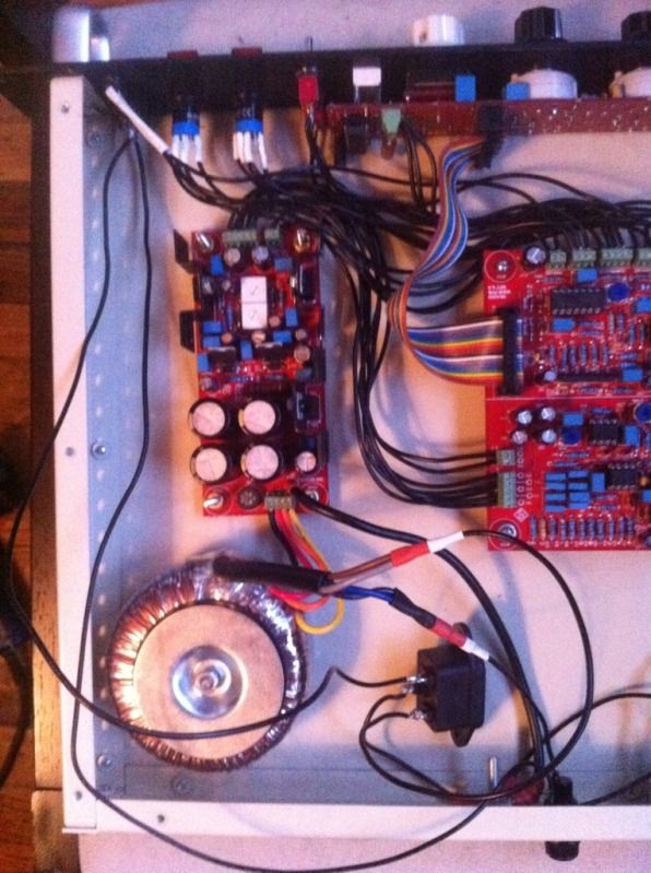
ALWAYS ALWAYS put a fuse between the LIVE and the transformer! always!

this is the only thing protecting you from direct mains voltage in the event of a mistake in your wiring.

the dots signifiy the start of the turns/winding and should be used to determine how you connect them for your outlet.
eg. for USA dual 110v-130v winding should be wired in parallel, whilst paying attention to connect the two dotted ends and keep correct phase in both windings.

i suggest you post clear pictures BEFORE plugging in. the last thing we need is a crispy DIY enthusiast.
 
Yeah, if you're CERTAIN that you're using the triad TX (look at the TX it will say on the side, their logo looks like ][ ) Then follow what i was saying above.  As you have it now, you're wired for 230/240 not 110/120. 

IF YOURE NOT 100% SURE YOURE USING THE TRIAD FROM THE BOM DO NOT FOLLOW THIS THE COLORS MAY BE WRONG!!!

The fuse should be inline between the TX and the IEC so for instance:

top row is your IEC
hot lead (line)                              neutral            ground
|                                                        |                    |
fuse holder                                  on/off sw    um... to ground
|                                                        |     
Tx Pair (BL/PR)                      other TX pair(BR/GY)


Best way to do this is to get an IEC that has the fuse built in
http://www.mouser.com/Search/ProductDetail.aspx?R=6200.2300virtualkey69300000virtualkey693-6200.2300
cant go wrong with that... well... yes you can, but please be careful.
 
Yeah i gotta +1 with Kep, before you try to turn this thing on again, post some pics and let us take a look at whats going on under the hood there.  i've gotten bit before, its not fun!

 
Yes, I can't agree more with above.

One thing, SR1200 - I actually advise against using the Neutral as your on/off switching, think I have discussed this here before.  Reason being, if you connect the Neutral to the power switch, and hard wire the Line (after the fuse) directly to the transformer, then there is always live voltage inside the unit, depending on fuse size used, there could be plenty to give someone a nice jolt before the fuse ever kicks in.
 
ruckus328 said:
sr1200 said:
Im still at a loss on my second unit.  im beginning to think that perhaps i have a bad relay.  What pins can i jump on the compress in/out relays to test my theory.

You need to systematically narrow down where the problem is.  You haven't really given any info on what issues you're seeing now.  There's no way to jumper the relays with them installed, you would need to depopulate them completely to hardwire them into compression mode, but honestly a simple multimeter on continuity test will tell you if they're working or not.

Step 1 is verify the audio path is intact and passes audio -

-Remove ALL IC's except for The input 5534's (U3/U5) and output 5532's (U8/U4)
-Jumper pins 1 & 8 on both audio VCA's (U11/U17) (use a diode leg or buss wire, etc)
-Take the sidechain out of the equation completely.  Lift one end of R12,R13, & R33 (located near the external in connector).  This will severe the singal going to the sidechain, and will let you verify your audio path is working first.
-Now check if the unit passes audio
-If it does, install the Audio VCA's and check again that it passes audio

Report back, we'll go from there.

I'm passing audio but I'm not compressing where should I start testing continuity to figure out where the problem is? I'm also not getting any AC Voltage at TP 8
 
i did jump the resistor by the threshold pot. I buzzed out my ribbon cable and it seemed good. And the LED  meter is responding to movement from the gain knob but I'm getting no other response from my control board (threshold, attack...) I'm assuming it must be a bad solder joint but I'm a newbie at this. This is my first build without tubes
 
I did this a couple times.... make sure you have the input to the inputs (middle two jacks), the unit passes audio from the output to the input (reversed) in bypass.  It stumped me for like 20 min on my first build, i usually put my input jacks first then output, but because of the layout of the PCB, i reversed it.

Ruck (your inbox was full, tried to respond to your PM) and I never really paid it much attention since my fuse was built into my IEC, but yeah, i see your point... I guess my thinking was that if everything was wrapped up nicely, it wouldnt really matter, and if anyone is working on this thing while plugged in... they know the risks involved.  But perhaps a reason to go back in and swap the two pairs (if thats even how I did it... its been months)
 
ruckus328 said:
Yes, I can't agree more with above.
+1

One thing, SR1200 - I actually advise against using the Neutral as your on/off switching, think I have discussed this here before.  Reason being, if you connect the Neutral to the power switch, and hard wire the Line (after the fuse) directly to the transformer, then there is always live voltage inside the unit, depending on fuse size used, there could be plenty to give someone a nice jolt before the fuse ever kicks in.
something like this.

Don't blindly believe what a switch or wire colour coding implies. Pull your mains plug off the wall. This will especially be true for some european mains plugs where you'd have a 50/50% chance in guessing which wire will be life or neutral and it might be different again the next time you connect it to the wall.
 
sr1200 said:
I did this a couple times.... make sure you have the input to the inputs (middle two jacks), the unit passes audio from the output to the input (reversed) in bypass.  It stumped me for like 20 min on my first build, i usually put my input jacks first then output, but because of the layout of the PCB, i reversed it.

I'm sorry i'm not following can you explain a little differently? are you talking about the xlr inputs and out puts?
 
ruckus328 said:
buildafriend said:
Harpo said:
@buildafriend, some remarks.
1) Mains fuse seems missing.
2) From your profile location info you seem to be US based, so the mains transformer primary windings will be wired in parallel for 120VAC mains. Your pic seems to show the primary windings hooked up in series for 230VAC mains. This will hum, because the transformer now only transforms to half of its secondary voltages. Not enough for your PSUs regulators.
3) A toroidal transformer for usual radiates the largest field where the leads come in/out. You might twistturn it about 180 degrees, so leads are closest to your case corner. Distance is your friend.
4) Twist each pair of at least your audio-In hot/cold wires, so the balanced line receiver has a chance to cancel out common mode induced garbage.
5) Missing resistors at the audio-VCAs?

All remarks and advice are appreciated
1) I don't know where the fuse should be in the circuit. Maybe on the hot wire of the primary of the power xfrmr? as you can see I have a fuse that is separate from IEC connector. I am not sure where it should be connected.
2) Do you mean the mains transformer primary windings on the positive side(the primaries with the dots)? If anyone could rig together a fast wiring diagram it would be a huge help. It seems the one I used earlier in this thread is not for the US.
3) Thanks! Will do!
4) Hm.. I never knew that helped cancel anything out. Does that even matter though since this is an unbalanced circuit? I mean I'll do it, it seems to be something that everyone is doing. I bet they are doing that for a reason.
5) Oh it says not to throw those in somewhere in the build guide. Certain resistors on this board are only for use with certain chips. The board also accepts the original gold and black can DBX VCA's

Wow I just learned a lot.

Harpo, if you have anything to add please be my guest, but:

1)  Fuse should always go between line (L) on the IEC and the Power Switch.  Power switch is then wired to transformer primary.

2)  Your transformer will come with an instruction sheet of how it gets wired for 120V or 240V.  For 120V, you want to wire the transformer primaries in parallel.  For the VPT36-1390 transformer only - this means tie Blue/Violet together, and tie Gray/Brown together.  Blue/Violet is you Hot, and gets connected to your fuse.  Gray/Brown is your Neutral, and should be connected to Neutral (N) on your IEC.

4) It's done for the reason Harpo already explained. This is a balanced circuit, it's not unbalanced.  If you plug in an unbalanced connection on the output it will load down the 5532 output chip, eventually probably killing it.

5) Nowhere that I know of.  Those two resistors need to be installed for THAT218X chips, otherwise no compression or makeup gain will be possible.
I did my best trying to figure out the power wiring...

I think I followed your instructions well.

Blue and purple are together

Gray and brown are together

L hits the common tab on the switch

Other pin on the switch go's to the fuse

other side of the fuse connects to blue and purple

Brown and gray go to N on the IEC

ground.. ground. 

What size fuse?(i need to know this for my rev F 1176's too, i have the fuses on those bypassed)

I also installed the resistors near the that 218 chips

23a87ecb.jpg
 
buildafriend said:
what size fuse should i throw in here?
For your 50VA Triad toroidal transformer with 86% efficiency @ 110-120VAC mains from the link you provided from previous page ?
Size that fits for your fuseholder (from your pic probably 5x20mm).
Fuse rating 630mA/T should do the job.

begin edit:
(i need to know this for my rev F 1176's too, i have the fuses on those bypassed)
Scary. Transformer will be different from your SB4000 mains transformer, so noone can give you a serious advice without further information. This question would better be placed in a 1176 related thread.
end edit


Order of this circuit loop is IEC-L -> fuse -> switch -> transformer -> IEC-N. Just have a look at 'this' from my previous post.
 
I had a few points on the main pcb I hadn't soldered! That's what I get for rushing.

I'm up and running and it sounds great. Thanks everyone
 
Anybody know of a distortion analyzer software like RMAA that works with a mac? I'm trying to do the THD section of the calibration. I have a PC at the house but my studio is based around a mac
 
Just view the harmonics under a spectral analyzer.  download blue cat's cuz it ges down to -120dbfs:

http://www.bluecataudio.com/Products/Product_FreqAnalyst/

Export a 1K test tone and look at the output of the unit in the analyzer.  You'll be able to see the 2nd harmonic node at 2K.  Make sure your gain is at 0 and the "external in" is engaged while you're doing the test so you ensure there is no signal present at the control port of the VCA (which will skew the results).
 
I'm having problems calibrating the right side of the T1 & T2 Filters.
TP11 is reading 4.0
When I try to adjust the voltage at TP12 with VR5 I'm only getting a range from 2.51-1.016.

thanks yall
 
Back
Top