SB4000 Support Thread

GroupDIY Audio Forum

Help Support GroupDIY Audio Forum:

This site may earn a commission from merchant affiliate links, including eBay, Amazon, and others.
Hey fellas, I went back and read through this thread again and found some info. So I am indeed getting voltage to TP10 while the Internal Sidechain switch is depress because that's what it's supposed to do. I'm a dummy... But the other issue with the threshold pot not working is throwing me for a loop. I had the 47k resistor installed at r169 with no jumper. It was compressing and showing gain reduction on the vu mater but with no control on the thresh pot. So I cut out the 47k resistor and installed a jumper. Now I have no compression, nothing on the meeter and no threshold control.  ???  I went threw and tested continuity on the ribbon but that tested fine. It's not the jumpers at the VCA's because I hear compression yesterday. Should I reinstall the 47k resistor and then jumper?
 
Just an update if anybody is reading this... The continuity of the ribbon cable tested great with the connectors crimped on. But, when I hooked it up to the main and control PCB's I had a few shorts. If pin one is next to the arrow on the PCB's then here are the pins that are shorting out. (Pin 8 to pin 10) (pin 11 to pin 13) (pin 18 to pin 17) I've tried tracing every thing down on the schematic but I'm just not sure.
 
Mike Mike said:
Just an update if anybody is reading this... The continuity of the ribbon cable tested great with the connectors crimped on. But, when I hooked it up to the main and control PCB's I had a few shorts. If pin one is next to the arrow on the PCB's then here are the pins that are shorting out. (Pin 8 to pin 10) (pin 11 to pin 13) (pin 18 to pin 17) I've tried tracing every thing down on the schematic but I'm just not sure.
Check a page or two ago, my kit had a faulty connector at one end of the cable that had me stumped for a couple weeks.  My problem was that I was checking continuity at the exposed wire ends and not at the terminals in the boot.  May or may not be relevant to your issue but it's a thought.
 
Hey Bowie, yeah I've tested the inside of the connectors with the help of some resistor leads, my DMM probes wouldn't fit. I also tested the headers with the ribbon cable plugged in via the twenty solders joints on each pcb. The connector testing showed I had no wires shorting out but when I plugged it in there were shorts in three places. Are we supposed to have any shorts with it plugged in? 
 
Mike Mike said:
Hey Bowie, yeah I've tested the inside of the connectors with the help of some resistor leads, my DMM probes wouldn't fit. I also tested the headers with the ribbon cable plugged in via the twenty solders joints on each pcb. The connector testing showed I had no wires shorting out but when I plugged it in there were shorts in three places. Are we supposed to have any shorts with it plugged in?
There will be continuity between certain points, at various resistance, but I can't really say which to look for.  Before I discovered my problem, I went over the schematic and became familiar with the designation and routing of each pin so I could see if they were behaving normally.  This sounds like you've done that.  I don't have an SB4k in my possession that I can check for you.  Are those same points shorting on the board(s) when it's unplugged?
 
Bowie said:
Mike Mike said:
Hey Bowie, yeah I've tested the inside of the connectors with the help of some resistor leads, my DMM probes wouldn't fit. I also tested the headers with the ribbon cable plugged in via the twenty solders joints on each pcb. The connector testing showed I had no wires shorting out but when I plugged it in there were shorts in three places. Are we supposed to have any shorts with it plugged in?
There will be continuity between certain points, at various resistance, but I can't really say which to look for.  Before I discovered my problem, I went over the schematic and became familiar with the designation and routing of each pin so I could see if they were behaving normally.  This sounds like you've done that.  I don't have an SB4k in my possession that I can check for you.  Are those same points shorting on the board(s) when it's unplugged?

I'm assuming they would be... Would continuity really change if there was power running through it?
 
So I'm definitely getting voltage change on the threshold pot. When I put my black prob on ground and red prob on the top lead of the threshold pot I get a variation in voltage as I turn the pot left to right. All the way CCW is -10.8vdc and all the way CW is -12vdc. I'm not sure why its not compressing more or less when I run audio through it.
 
Mike Mike said:
When I put my black prob on ground and red prob on the top lead of the threshold pot...
whatever the top lead might be, you want to measure the DC voltage at pot wiper, the pots center pin (arriving at J18-pin1 and J6-pin1), in respect to 0V reference voltage.
... I get a variation in voltage as I turn the pot left to right. All the way CCW is -10.8vdc and all the way CW is -12vdc.
check why +12VDC doesn't arrive at the pots CCW end with R169 shorted out/zero ohm (readout at pot wiper should vary from +12V to -12V).
With R169 not shorted out (47K), readout at pot wiper should vary from +0.37V to -12V on paper (the pot comes with +/-20% parts tolerances, so the pots CCW end voltage in this series string might vary by a similar amount).
From your previous posts I have no idea what parts you have fitted, left out or shorted out by a jumper. (jumpers have parts designators as well, so we're talking about the same subject).
 
Mike Mike said:
Bowie said:
Mike Mike said:
Hey Bowie, yeah I've tested the inside of the connectors with the help of some resistor leads, my DMM probes wouldn't fit. I also tested the headers with the ribbon cable plugged in via the twenty solders joints on each pcb. The connector testing showed I had no wires shorting out but when I plugged it in there were shorts in three places. Are we supposed to have any shorts with it plugged in?
There will be continuity between certain points, at various resistance, but I can't really say which to look for.  Before I discovered my problem, I went over the schematic and became familiar with the designation and routing of each pin so I could see if they were behaving normally.  This sounds like you've done that.  I don't have an SB4k in my possession that I can check for you.  Are those same points shorting on the board(s) when it's unplugged?

I'm assuming they would be... Would continuity really change if there was power running through it?
No, what I'm asking is if those points are shorting on the pins of the socket, before you plug in the ribbon cable. Or, if it's only after you plug the ribbon cable in.
 
Bowie said:
Mike Mike said:
Bowie said:
Mike Mike said:
Hey Bowie, yeah I've tested the inside of the connectors with the help of some resistor leads, my DMM probes wouldn't fit. I also tested the headers with the ribbon cable plugged in via the twenty solders joints on each pcb. The connector testing showed I had no wires shorting out but when I plugged it in there were shorts in three places. Are we supposed to have any shorts with it plugged in?
There will be continuity between certain points, at various resistance, but I can't really say which to look for.  Before I discovered my problem, I went over the schematic and became familiar with the designation and routing of each pin so I could see if they were behaving normally.  This sounds like you've done that.  I don't have an SB4k in my possession that I can check for you.  Are those same points shorting on the board(s) when it's unplugged?

I'm assuming they would be... Would continuity really change if there was power running through it?
No, what I'm asking is if those points are shorting on the pins of the socket, before you plug in the ribbon cable. Or, if it's only after you plug the ribbon cable in.
Oh sorry, I'm slow lol. I just checked the header pins at both PCB's and the main PCB shows zero shorts between pins, but the control board showed shorts between 11 & 13 as well as 17 & 18. Plus, the short at 8 & 10 only exists when the ribbon is plugged in. Soooo...... ???
 
So I was playing around with the ration switch as I ran some tunes through the comp. With the wiper set in between two ratios the vu meeter shows 4dbs of gain reduction and my threshold pot works! I can hear and see compression. Do you all think my ratio switch has something to do with the unit not compressing?
 
Harpo said:
Mike Mike said:
When I put my black prob on ground and red prob on the top lead of the threshold pot...
whatever the top lead might be, you want to measure the DC voltage at pot wiper, the pots center pin (arriving at J18-pin1 and J6-pin1), in respect to 0V reference voltage.
... I get a variation in voltage as I turn the pot left to right. All the way CCW is -10.8vdc and all the way CW is -12vdc.
check why +12VDC doesn't arrive at the pots CCW end with R169 shorted out/zero ohm (readout at pot wiper should vary from +12V to -12V).
With R169 not shorted out (47K), readout at pot wiper should vary from +0.37V to -12V on paper (the pot comes with +/-20% parts tolerances, so the pots CCW end voltage in this series string might vary by a similar amount).
From your previous posts I have no idea what parts you have fitted, left out or shorted out by a jumper. (jumpers have parts designators as well, so we're talking about the same subject).
I apologize Harpo. I did not see your post. I have the R169 shorted out and just checked the threshold wiper at J18 and J6. There is still only about a two volts difference at these points. So yeah, somethings not right with that. I wonder what could be keeping it from its 24volt potential.
 
WOOHOOO I found the issue!!!!! I'm such a rookie. I forgot to solder the three pins of the pot to the small adapter PCB. Thank you guys for putting up with me.  ;D
 
I just wanted to chime in with another success story!  Although it took me a couple of months to actually find time to piece it all together and calibrate (kids, fever from kids, job, that whole bit), it did eventually happen.  I ordered the front panel, boards and kit through Serpent Audio and it arrived within maybe 2 days.  I also used parts from Hairball, Mouser, Digikey, and Par Metal.  The PCBs are just excellent!!  The physical quality is top notch, but the real bonus is that  nearly every bit of info you could imagine has found its way onto the markings on the boards.  I've put together a couple of CAPI VP28 pres and a handful of other smaller kits, so I had enough experience to know to sort and test all the pieces before hand (I laid out everything on paper with painter's tape and labelled appropriately while I tested with my multi-meter).  It's a lot of time up front, but I can say that when I powered up the PS, and then later the whole unit, it all worked first time!  Outside of my own self-inflicted confusion when calibrating, I had absolutely nothing to debug!  This thread was super helpful as well.  I took notes on certain situations (like controlling the LED brightness on my meter (from Hairball)), and the many pictures helped make sure I had switches and those sorts of things lined up.  I did contact Mike once via email and he answered promptly.  One thing I noticed that's missing from the first post of this thread is the schematic.  That was definitely useful for knowing resistor values and jumpers (and would have answered my email question) for the various configurations.  Luckily I found it somewhere in the middle of the thread... might be worth while to post that upfront if possible with the rest of the materials (it was named SB4000_REV4_FORUM.pdf for those that want to pull it up via Google).  Google is really your friend "sb4000 groupdiy <part/board location/keyword>" spit out all sort of answers for me...

The unit works, looks, and sounds great! What an excellent community as well; very knowledgeable people with no egos and plenty of patience.  Many thanks to those that have contributed.     
 
Hello,

got my SB4000 Rev.4 put together today... have some big problems tough:

- voltages are correct, directly from the power supply board (about 11,9V, -11,9V, +14,95V and so on..), but instead of -15V, i get a whopping -23,5V! Everything is built correctly. Used 1k33 resistors instead of trimpots. Maybe a defective 337?

- only get a very distorted signal out of it, on both channels. sounds like oscillating when "unity gain" trimpots are used. also, no compression, make-up gain is the only knob that works.
overall noise level is very very high. barograph works, when R34 or R36 is touched.
nothing on TP11 or TP12.

no reaction on all other calibration trimpots except "unity gain"

swapped already the VCAs, the TL074s and the TL072 and the ribbon connector. Is this maybe related to the wrong negative voltage supply?

please help... i have a few days off now  8)
 
Kontra said:
- voltages are correct, directly from the power supply board (about 11,9V, -11,9V, +14,95V and so on..), but instead of -15V, i get a whopping -23,5V! Everything is built correctly. Used 1k33 resistors instead of trimpots. Maybe a defective 337?
Most likely either a broken LM337 (U20) or diode 1N4002 (D25) fitted reversed.
Without the PSU operating correctly (before connecting the SB4000 in order to not blow up parts), any other measurement doesn't make much sense.
 
I have DBX 202C cans installed (with proper accommodations made, as per the schematic) and while I can get audio to pass through when the comp is engaged, as soon as compression kicks in, the signal cuts out.  Does this indicate something wrong with my DBX VCA?  I build one with THAT chips recently and the only thing I did differently this time was use the Gold can and made the adjustments listed on the SB4k schematic.
Thanks.

EDIT;  I installed the other VCA and everything worked fine so I took another look at the first VCA.  I has soldered it in very lightly, in case it needed to be removed.  Apparently, it wasn't enough heat to really bond wit the thick pins on the VCA, hence the skectchy performance.  Everything's fine (except for the fact that I spent half a day chasing ghosts).  The tone of the unit sounds exactly the same that the version I made with THAT VCA (slight softness in the upper-mids and highs, thickness in the upper-bass and low-mids), though the DBX gold can build might be a little more transparent in the nature of it's compression.  I expected the opposite to be true.
 
What can cause crosstalk in this unit?  If I send a signal into just the right channel while listening to the left, a little bit of thuddy, distorted music can be heard.  I can even see it on the input on the bargraph VU.  The odd thing is that it does not leak into the other channel if I reverse it.  The unit is fully functional and working well.  I just need to know what direction to go in to track this down as I've never dealt with it before.
Thanks.
 
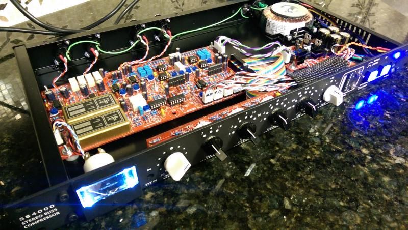
Here's a pic of the completed DBX Gold can build.  Still needing someone to shed some light on the issue mentioned above (bleed from channel 2 to channel 1).
IMAG1152_zps9516c204.jpg
 

Latest posts

Back
Top