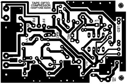
Scott Hampton Class A Opto Comp with schemo and parts list!

GroupDIY Audio Forum

Help Support GroupDIY Audio Forum:

This site may earn a commission from merchant affiliate links, including eBay, Amazon, and others.
jdiamantis,

The opto sidechain I was reffering to is this one

It's a little different than the one that Scott Hampton designed. You'dd see in the sidechain schematic that changing the ratio pot inserts a series resistance that acts to limit the amount of current going to the LED. The rectified, thresholded compared, and timed signal is a voltage proportional to the amount 'over' threshold the input is, and the ratio control determines the degree of compression by altering the amount of current sent to the vactol's LED.

Cheers,

Kris
 
optofixcopy.jpg
 
Does anybody know where to get those little extruded cases Scott used? They would be prefect for a multitude of little projects.

Cheers,

elco
 
to make a stereo version of this - is it just as simple as having 2 boards, and making the pots 2 per shaft? (I do not know what this is called exactly) And maybe matching the fets?

I would like to be able to stack the boards and fit a stereo version into a similar sized enclosure for my live keyboard rig.
 
[quote author="DrFrankencopter"]The opto sidechain I was reffering to is this one

It's a little different than the one that Scott Hampton designed. You'dd see in the sidechain schematic that changing the ratio pot inserts a series resistance that acts to limit the amount of current going to the LED. The rectified, thresholded compared, and timed signal is a voltage proportional to the amount 'over' threshold the input is, and the ratio control determines the degree of compression by altering the amount of current sent to the vactol's LED.
[/quote]
Dr. F,

But this side chain is not for FF opto compressor, but a FB opto compressor. Actually, it's a FB with some FF summed in, similar to the LA2A side chain when operating in "compress". The circuit will act like a FF circuit until the opto is of a low enough resistance to begin to reduce the gain to the side chain, via the attenator formed by the series resistor R43, and shunt resistance formed by the series connection of R44 and the opto.

Changing the LED current in this circuit will change the ultimate ratio of the circuit. Now, if you changed the side chain take off point prior to the 4.99kohm resistor R43, as opposed to between the R43 and R44 a 1kohm, then changing the LED current would not change the ratio, as it would be a pure FF circuit. It would merely change the rotation point of when compression would reach infinity to one ratio.

If you had an opto that had a log transfer curve, such that a decade decrease in reistance was proportional to a linear change in diode current (lets say 1ma for a change from 100k to 10k, and another 1ma for a change from 10k to 1k, etc) then, if you changed the current in the LED vs input to the side chain (or changed the gain of the side chain), you could control the ratio in a FF circuit. You would need a dc to log converter in the side chain, to make that circuit work.

However, these devices are (roughly) purely linear in tranference, in that a decade change in resistance in the cell is proportional to a decade change in LED current. There is no way you could design a FF circuit with this kind of element that would allow you to adjust the compression ratio by varying the current through the LED by changing gain of the side chain.

jD
 
@milkmansound:
What you describe would just be the first step to a real stereo compressor since GR would be different on both matched mono unit. You just matched the parameters but the sidechains work independently... have to look at the schem again, sorry, no solution right now...

Martin
 
Many thanks for all the effort on this thread. As ever much of it is way above my head, but I get the feeling the general consensus is that this not so simple "simple" compressor is worth building. It even seems to be PRR approved!!!
Stephen
 
Hey Folks,

Has anyone tried a home etch from Ptown's redraw? I've never done a hom etch
before and so this will be the first. I noticed the edge of the traces are
rasterized and a little fuzzy. Will this effect the etch at all?

I'm kinda of wet behind the ears here with this.

Cheers

Matt
 
Hm

It could be that I saw them by Reichelt/Germany, but maybe they are not the same type. Something about 12 ? i guess.

What Programm open those xls Files ? I would like tho see the Boom Matta posted.

Best Regrads: Jasmin
 
Hi Jasmin,

It is opened with Microsoft Excel. If you don't have it there is a free
viewer on the MS site, but you can open it with another programme like Open
Office, or any piece of software that can read Excel Spreadsheets.

If someone has access to the Acrobat distiller and can convert it to a .pdf
and mail me I'll be happy to host it.

Cheers

Matt
 
Those enclosures look a lil like the vero eurocard modules for the 3U racks - Here's a PDF: http://notapplicable.co.uk/audiolab/km6ii-subrack.pdf
 
[quote author="matta"]Hey Folks,

Has anyone tried a home etch from Ptown's redraw? I've never done a hom etch
before and so this will be the first. I noticed the edge of the traces are
rasterized and a little fuzzy. Will this effect the etch at all?

I'm kinda of wet behind the ears here with this.

Cheers

Matt[/quote]

as long as there's a continuous path, the quality of the edges are irrelevant
 
[quote author="Housemeister"]:oops: i had never used excel,

thanks Matt[/quote]

Lucky you.

Does anyone know if the enclosures used for the Al-e-sis Micro limiter and Micro verb are available to individuals? I have one Micro limiter in a rack tray that can hold three of these boxes. It would be cool to put the Tape Opto next to it.
 
re: opto slopes
I would add that the product line of VTL5Cx parts have some quite different characteristics. Turn on and off times vary quite a bit, as well as their slopes and min/max resistances.

I've been fooling around with a stereo opto-comp circuit using VTL5C2's for some time. I've found it's necessary to use a circuit test jig to select pairs because there's quite a bit of variation in the values, even from the same batch. I test the VTL's with a voltage/current that is typical for my circuit, and measure the cell resistance. My target is the 10k-20k range for the circuit to work as intended, but I see values from 8k up to 40k in the test jig. Most tend to fall into my range, but there are numerous outliers.

lots of great info here:
http://optoelectronics.perkinelmer.com/catalog/Category.aspx?CategoryName=VTL5C+Series
 
Back
Top