Should phantom power be supplied by a linear supply?

GroupDIY Audio Forum

Help Support GroupDIY Audio Forum:

This site may earn a commission from merchant affiliate links, including eBay, Amazon, and others.

Lerok

Active member
Joined
Jan 17, 2018
Messages
37
Location
Fort Wayne, Indiana
Hi, designing a power supply for a modular preamp box I'm putting together - I'm currently running +/-15vdc out of a center tapped transformer for power for the pres themselves, and was a little curious as to your guys' thoughts on the impact running phantom power through a cheaper switching supply would have on the sound - I'm assuming any small sonic difference from a switching supply on a mic's internal circuit would be amplified once it hits the pre stage, but I know Douglas Self's small signal audio design recommended a voltage tripler hooked up to the positive rail.

Any thoughts?
 
You'll need a good amount of filtering on either kind of supply.  A linear supply will have 120Hz (or 100, depending on where you live) ripple, while a switching supply will have higher frequency noise.  But almost any piece of pro gear you buy these days will have all switching supplies. 
 
If you use a quality vaguely new SMPS, it will be quieter than even a really good linear supply. Linear supplies are actually pretty crude if you think about it rectifying AC and then brute forcing it to be quiet with massive filter caps. Modern SMPS like the ones from MeanWell can be very good leaving 100mVpp of high frequency ripple that is pretty easy to filter out with even small parts. But there are pitfalls to making an SMPS supply. The main one is that grounding has to be correct (although that is probably a prerequisite for any circuit really). Another pitfall is that you have to load an SMPS at least 20%+ or it will run in "hiccup" mode and emit low frequency whistling noises. Another is filtering high frequency noise. But if you pick the right size and maybe even add a little bit of a load and then follow that with a simple capacitance multiplier, it should be completely silent with no mains. I used to preach using a CLC filter but a CM is more than good enough, cheaper and probably better then a CLC anyway.
 
In theory the phantom supply should not matter much. The phantom voltage is fed common mode to both inputs through precision resistors so noise will cancel out due to the input circuit's common mode rejection. Good practice suggests you shouldn't  rely completely on CMRR and start with a relatively clean (well filtered) phantom voltage supply.

JR

 
JohnRoberts said:
Good practice suggests you shouldn't  rely completely on CMRR and start with a relatively clean (well filtered) phantom voltage supply.

That was my general thought process as well, though from what those above you have said, it seems like as long as I put together/purchase a relatively quality switching supply, noise shouldn't be a major issue. Thanks a ton, just wanted to confirm!

squarewave said:
If you use a quality vaguely new SMPS, it will be quieter than even a really good linear supply. Linear supplies are actually pretty crude if you think about it rectifying AC and then brute forcing it to be quiet with massive filter caps. Modern SMPS like the ones from MeanWell can be very good leaving 100mVpp of high frequency ripple that is pretty easy to filter out with even small parts. But there are pitfalls to making an SMPS supply. The main one is that grounding has to be correct (although that is probably a prerequisite for any circuit really). Another pitfall is that you have to load an SMPS at least 20%+ or it will run in "hiccup" mode and emit low frequency whistling noises. Another is filtering high frequency noise. But if you pick the right size and maybe even add a little bit of a load and then follow that with a simple capacitance multiplier, it should be completely silent with no mains. I used to preach using a CLC filter but a CM is more than good enough, cheaper and probably better then a CLC anyway.

I've been looking at a fairly affordable MeanWell supply, seems to be around $15 US, which is absurdly cheap - by grounding, I'm assuming there aren't any crazy tricks? I'm familiar with connecting ground to 0v Ref over one resistor/cap, and connecting the 0V ref on my circuits to this and not chassis/xlr ground, but given that most of my electronics experience prior to this has been on battery-powered pedals, grounding is a bit of a limited area for me (though definitely one I need to read on before I tackle any project).
 
Lerok said:
That was my general thought process as well, though from what those above you have said, it seems like as long as I put together/purchase a relatively quality switching supply, noise shouldn't be a major issue. Thanks a ton, just wanted to confirm!

I've been looking at a fairly affordable MeanWell supply, seems to be around $15 US, which is absurdly cheap - by grounding, I'm assuming there aren't any crazy tricks? I'm familiar with connecting ground to 0v Ref over one resistor/cap, and connecting the 0V ref on my circuits to this and not chassis/xlr ground, but given that most of my electronics experience prior to this has been on battery-powered pedals, grounding is a bit of a limited area for me (though definitely one I need to read on before I tackle any project).

Yes a bunch of us have used that MeanWell supply, and there are threads about it, and a link to another site with extensive noise test data.  They are fine with a little more RC or LC filtering. 
 
EmRR said:
Yes a bunch of us have used that MeanWell supply, and there are threads about it, and a link to another site with extensive noise test data.  They are fine with a little more RC or LC filtering.

Thanks, Doug - I will go hunting for those threads later tonight, this forum is a cornucopia of good information haha.
 
Lerok said:
I've been looking at a fairly affordable MeanWell supply, seems to be around $15 US, which is absurdly cheap - by grounding, I'm assuming there aren't any crazy tricks? I'm familiar with connecting ground to 0v Ref over one resistor/cap, and connecting the 0V ref on my circuits to this and not chassis/xlr ground, but given that most of my electronics experience prior to this has been on battery-powered pedals, grounding is a bit of a limited area for me (though definitely one I need to read on before I tackle any project).
Yes, the little beige MW led supplies are actually really good. But again, 48V is only ~10mA per channel so if you only have one channel it's actually a bit of an issue finding one small enough. You basically have to use a 5W deal and then add a load resistor.

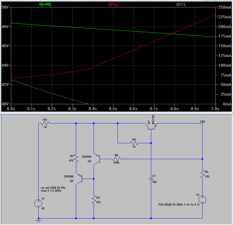
Note sure what you mean by the "0v Ref over one resistor/cap". Proper grounding is definitely a little tricky because it matters *where* various ground wires converge. There should be a single point at the ground of the power supply filter caps where a bunch of grounds connect through it's own dedicated path. This is sometimes referred to as "star ground" but in reality it's more like branches of a tree and that filter cap ground is where the tree trunk is planted in the "ground". More specifically, if you were to add the 48V SMPS, you would of course add the input to the mains but then run the + and - output into a capacitance multiplier circuit like this:

EDNAOL_2016JUN14_AN_03Fig2.gif


and then add a 100uF or so filter cap after that. Then take the ground of that point and attach it to the filter cap ground on the power supply (the "tree trunk").

However, there is another issue. Pin 1 of the XLR in is used for 48V return. So that needs it's own path to the filter cap ground on the power supply. If your enclosure is metal (recommended for mic pres), then usually pin 1 of the XLR in is connected to the chassis right at the input. This is because pin 1 is also the shield for shunting RF noise. That path from the XLR to the chassis should be as short as possible. The length of that path defines the wavelength of RF that can be radiated within the enclosure. This is why there are XLR inputs with a metal spike in the screw hole that stabs the metal panel when screwed tight and connects the metal chassis to pin 1 over a very short internal connection. So 48V returns through the chassis. This means that you then need to run a wire from the chassis (usually the same place where mains earth is bolted to it) to the, yes again, the filter cap ground on the power supply.

So yeah, this stuff can be tricky because everything I've said above is about *where* grounds are connected together.
 
squarewave said:
Linear supplies are actually pretty crude if you think about it rectifying AC and then brute forcing it to be quiet with massive filter caps.

Some would say "Crude" others would say "Simple". But you don't generally need 'massive' caps before a linear voltage regulator - just sufficient to give the voltage regulator enough to work with.
 
squarewave said:
Yes, the little beige MW led supplies are actually really good. But again, 48V is only ~10mA per channel so if you only have one channel it's actually a bit of an issue finding one small enough. You basically have to use a 5W deal and then add a load resistor.

Think this will be a bit of a non-issue for my personal use case, as I'm powering 16 mic pres off the supply, haha
squarewave said:
Note sure what you mean by the "0v Ref over one resistor/cap". Proper grounding is definitely a little tricky because it matters *where* various ground wires converge. There should be a single point at the ground of the power supply filter caps where a bunch of grounds connect through it's own dedicated path. This is sometimes referred to as "star ground" but in reality it's more like branches of a tree and that filter cap ground is where the tree trunk is planted in the "ground". More specifically, if you were to add the 48V SMPS, you would of course add the input to the mains but then run the + and - output into a capacitance multiplier circuit like this:

EDNAOL_2016JUN14_AN_03Fig2.gif


and then add a 100uF or so filter cap after that. Then take the ground of that point and attach it to the filter cap ground on the power supply (the "tree trunk").
.

So just going off my rudimentary knowledge of power supplies, the capacitance multiplier is just acting as RC filtering on the power source after the SMPS? Simple question, I know.

For the grounding, the way I'm understanding it, assuming I used a metal chassis (as recommended), a very rudimentary drawing would look something like

yCVTYDn.png

 
Lerok said:
Think this will be a bit of a non-issue for my personal use case, as I'm powering 16 mic pres off the supply, haha.
Ok. So something like a 250mA supply might be about right but also realize that you might only have one channel actually using 48V at any particular moment in which case you'll probably still need to load it to keep it out of hiccup mode. This is an annoying scenario where a dynamic load circuit might be worth exploring. Meaning there could be a circuit that adds a load to keep the SMPS out of hiccup mode but when more channels use 48V, the dynamic load decreases to divert current to the mics. But I can't really think of a specific circuit to do this at the moment.

Lerok said:
So just going off my rudimentary knowledge of power supplies, the capacitance multiplier is just acting as RC filtering on the power source after the SMPS? Simple question, I know.
Basically. A CM looks like a capacitor that is a lot larger than the cap on the base of the transistor (although in truth there are important limitations). This would normally not be suitable with an unregulated source like in a linear supply but an SMPS is almost always regulated (even the constant current ones usually are) so the CM works here without causing a voltage drop that is dependent on load. Although there is a 0.6V drop from the transistor emitter diode junction. Another benefit is that it keeps the SMPS output protection from kicking in which would occur if you just used a giant cap instead.

Lerok said:
For the grounding, the way I'm understanding it, assuming I used a metal chassis (as recommended), a very rudimentary drawing would look something like
Yup. That's right.
 
squarewave said:
there could be a circuit that adds a load to keep the SMPS out of hiccup mode but when more channels use 48V, the dynamic load decreases to divert current to the mics. But I can't really think of a specific circuit to do this at the moment.
What about a slightly increased voltage source, a drop resistor and a shunt regulator?
 
FWIW the small MeanWell spec sheet confirms no load is needed, it must be internally loaded.  I have not seen a failure to operate without a load. 
 
dogears said:
Mind walking me through that one?
With little or no load, Q2 is off and Q3 is on. This sinks current defined by R1 and / or R3 to set the minimum load. When load increases, the little bit of voltage drop of the capacitance multiplier turns on Q2 and turns off Q3 which takes out the min-load.

In practice C1 would probably be more like 100u, there should be a filter cap of maybe 470u or more on the output, there should probably be a protection diode across Q1 and the max voltages for Q2 and Q3 probably need to be a little higher.

The circuit as-is is limited to about 250mA though because the 48V will start to drop a little too much. Above 250mA, you would need a CM that uses a complementary pair of transistors but that would be two diode drops which necessitates a little higher source voltage (the bigger SMPS frequentyly can be trimmed up a few volts no problem) and a diode in series with  R4 maybe.
 
Came back this morning, lots of info to sift through, looking forward to it!

I'll check the spec sheet of the meanwell supply I intend to use, but fingers crossed it's internally loaded - thanks for all the help @squarewave.

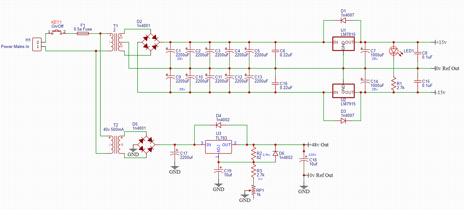
My current plan is to go linear for the +15/-15v supply, to avoid any load issues (given how much variance there is in preamp current draw depending on gain), and tack on a 48v switching supply to handle the phantom power. Ignoring the linear 48v schematic, this is where I'm at for the +/- 15v supply:

4cBiIvM.png


For the PCB, I'm planning on screw terminals for the mains voltages, and 6mm traces for everything, due to the high current...
 
Lerok said:
My current plan is to go linear for the +15/-15v supply, to avoid any load issues (given how much variance there is in preamp current draw depending on gain),
What? I've never seen a preamp's current draw vary more than 10% between utter silence and clipping.

Ignoring the linear 48v schematic, this is where I'm at for the +/- 15v supply:
Wow! 10 000 uF for less than 1.5A. Nothing wrong with it, but a tad over-engineered. Many would be satisfied with 5 times less.
I have come to favour the LM317/337 over the 78/79xx. They are more robust and less noisy. In addition, they simplify inventory.

For the PCB, I'm planning on screw terminals for the mains voltages, and 6mm traces for everything, due to the high current...
What high current? The 78/79xx are limited at less than 1.5A. That would suggest 0.5mm traces. Since space is generally not an issue, I routinely use 0.8mm (32mil).
 
Forgive my ignorance. I have had very little noise from JLM, Five Fish, and others including CAPI, and my own haphazard replications that I cloned from various PSU's linear supplies, they all seemed excellent. Despite the all in one and small profile os it that much of a difference? Once again forgive my ignorance.
 
Back
Top