SSL 9K & 4K (E Series) 500 / 51X NEW BOARDS Mic Pre Thread 2011

GroupDIY Audio Forum

Help Support GroupDIY Audio Forum:

This site may earn a commission from merchant affiliate links, including eBay, Amazon, and others.
Hi, i  just powered up and R2 exploded. Without meterboard everything is ok.
I think, there was extra copper on the meterboard with a short power to ground. But the image has lost.
Can someone tell me, where exactly i had to cut a trace on the meter board ?

Thanks
Wolfgang
 
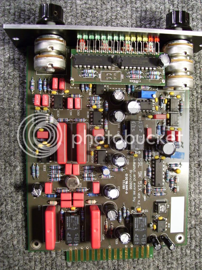
Yes there is a problem with grounding at the meter board.
When the led are in front of you, it’s the opposite the left side.

*when die LEDs von dir wegzeigen, dann ist es die linke untere Ecke.
Dort musst du ein wenig vom Kupfer abtragen.
 
I just checked the led PCB and it's a correct version . No short.
The problem remains the same. R2 is Smoking. I have to check again this evening.
 
I don’t think that there was ever a revision.
Just remove some copper at the left side at the LED meter board.
R2 is always smoking, when you have a grounding short.
 
Hi!

Has anyone had problems receiving the boards? I'm still waiting mine here in Spain... ???

Jay x
 
It usually takes about 3 weeks to get boards from Gustav to where I live in the US, but in the age of covid, don't be surprised if it takes longer.

I also do a lot of buying of CDs and records on Discogs, and it took me a month to get a CD from Holland, and I'l still waiting for a CD from Italy. I think that will be a month tomorrow.
 
Ricardus said:
It usually takes about 3 weeks to get boards from Gustav to where I live in the US, but in the age of covid, don't be surprised if it takes longer.

It's taking ages for my stuff from outside the EU to get here.
But inside the EU zone things have been pretty fast.

send a mail do pcbgrinder
 
Hi All,

So I built a pair of the 9K5s back in 2013...(I posted a reply somewhere in this thread at the time). They've generally worked well despite never having the polarity mod done.

Recently, I was DI-ing an electric guitar (via Bo DI, also tried my Radial JDI) and noticed that these suffer from noise a lot more than my other pre-amps (VP26s, Hairball Lola), which seems to go away when I touch the metal casing on the guitar lead.

Obviously it seems like there is a grounding issue, but as I hadn't done the polarity fix, I decided to do that first, just in case  it had some unintended side-effects. The fix went fine, but the problem persists.

So a couple of questions:

- Can someone who built there's without a metal L tray, confirm that they get the same behaviour?

- Pin 1 chassis ground isn't connected to anything if you don't use an L tray, so what have people been doing in their builds? The schematic is no longer available (I've got the v.4.2 boards), so I'm just guessing, but it seems odd that the chassis pin doesn't connect to anything unless you build with a tray, so I'm wondering whether that's my problem?

Cheers,

A
 
taliska said:
- Pin 1 chassis ground isn't connected to anything if you don't use an L tray, so what have people been doing in their builds? The schematic is no longer available (I've got the v.4.2 boards), so I'm just guessing, but it seems odd that the chassis pin doesn't connect to anything unless you build with a tray, so I'm wondering whether that's my problem?

If Pin 1 connects to the L Tray but you didn't used an L Tray tray, then you have to connect it to the Front Panel. Pin 1 connects to Chassis. Chassis is Shielding if connected to ground

Of course the schematic is available, all the schematics posted in this forum are available in some other members computers.

 
Ricardus said:
I thought the polarity issue had long been fixed by the 4.2 rev of the boards?

I don't believe so. After various people noticed the issue back on page 10? Bruno posted a pdf with the required fix and that is clearly on a marked up version of the 4.2 schematic:

bruno2000 said:
Here ya go!

It's even in the pdf file name. I'll attach it here again for convenient reference.

A.
 

Attachments

  • SSL 9K 51X 42xSIGPolFix.pdf
    215.7 KB
Whoops said:
If Pin 1 connects to the L Tray but you didn't used an L Tray tray, then you have to connect it to the Front Panel. Pin 1 connects to Chassis. Chassis is Shielding if connected to ground

Of course the schematic is available, all the schematics posted in this forum are available in some other members computers.

Ok, thanks for the info. I thought that might be the case, I just hadn't seen anyone else doing it in their tray-less builds.

As it happens I just found a couple of L-trays I had left over hidden in the corner of my room, so I might try and retrofit them at some point to fix the issue.

Thanks!

A.
 
taliska said:
Ok, thanks for the info. I thought that might be the case, I just hadn't seen anyone else doing it in their tray-less builds.

As it happens I just found a couple of L-trays I had left over hidden in the corner of my room, so I might try and retrofit them at some point to fix the issue.

Thanks!

A.

For now try a Crocodile clip connected between Pin1 and the front panel (or to any POT casing that touches the front panel)
 
taliska said:
I don't believe so. After various people noticed the issue back on page 10? Bruno posted a pdf with the required fix and that is clearly on a marked up version of the 4.2 schematic:

I just pulled one of these from my rack and I pulled the That 1646, and pin 8 of the chip goes to pin 2 on the edge connector, and pin 1 of the chip goes to pin 4 on the edge connector. That should be correct. The spec sheet for the 1646 says Pin 8 in the chip is +.

Page 10 was from 2011, and at one time I read the whole thread and I thought they talked about fixing that bug in a later rev.
 
Ricardus said:
I just pulled one of these from my rack and I pulled the That 1646, and pin 8 of the chip goes to pin 2 on the edge connector, and pin 1 of the chip goes to pin 4 on the edge connector. That should be correct. The spec sheet for the 1646 says Pin 8 in the chip is +.

Page 10 was from 2011, and at one time I read the whole thread and I thought they talked about fixing that bug in a later rev.

I think Bruno mentioned that he was going to fix it, but I'm not sure that he ever did as far as I can tell. Or to be more specific, if he did, then he never rev'd the version number, which kind of defeats the point!

If you look a few comments above the one I originally quoted, there's this comment:

kquick said:
One down three to go.  With one small problem the unit works very well except none of the LED's work.  It passes audio (Sounds Great) and all of the switches and pots work,  just no LED's.  When I turn the 48 volt switch on the power supply for the API 500 rack I get a slight Led glow from the 48 volt LED on the SSL9K if I turn it on.  This one has me stumped I disconnected the meter bar to check just the switch LED's still no power there. I know there are different voltages for the 51X but I did not see any alternative parts in the BOM thinking maybe I used something I was not suppose to.  I triple checked for shorts found none. I included pictures maybe some one can see if I did something wrong or have an idea were to start looking.

100_1048.jpg
100_1044.jpg
100_1038.jpg


Thanks
Kim

In this comment you can clearly see that the board is the v.4.2 rev and this comment precedes everyone's discovery of the issue and Bruno's fix comment, so I still think v.4.2 needs the fix.

Oh, and the issue isn't with the layout of the THAT1246 part of the schematic as I understand it from the comments.

The footprint of the relay is mirrored. This means it will get energised in the opposite direction and effectively swaps the default and energised positions of the relay.

At least that's my understanding of it...it's been A LONG TIME since I last looked at a schematic! LOL.

A.
 
I don't exactly follow the explanation. The polarity relay comes after the output of the 1646. The default position of the relay is unenergized, and the output of the positive pin goes to pin 2 of the edge connector in that state.

All I'm saying is if the positive pin of the output chip goes to pin 2 of the edge connector it seems to be wired right in my limited experience.
 
Whoops said:
For now try a Crocodile clip connected between Pin1 and the front panel (or to any POT casing that touches the front panel)

Good idea. I'll solder a cable to the casing of one of the pots and put a ring connector on the other end to screw through the mounting hole on the pcb that is connected to pin 1.
 
Back
Top