SSL 9K Mic Pre

GroupDIY Audio Forum

Help Support GroupDIY Audio Forum:

This site may earn a commission from merchant affiliate links, including eBay, Amazon, and others.
MartyMart said:
My bad - I meant 50v !!!
35V should be ample. 48VDC phantom -> 3K4 or 2x 6K8 in parallel from a preamp with mistakenly engaged phantom-switch -> 2x 10K in parallel to gnd at the ballancer board = 28.57V. ;)
 
hey guys,
sorry to bug you guys with this but I just want to make sure I'm using the right bits.

I'm I cool if I go with this?


channel_bal_parts.jpg


thanks >
 
I'm sure this was just a typo, but just to be sure, let me point out that the silk screen layer in your screenshot says:

100uF, not 1000uF like you typed.  I'm sure you know, just pointing out the obvious just in case.
 
100uF/35V seems sufficient for a HPF @ 0.16Hz and size will fit the pcb probably better than a 1000uF part. ;)
100nF is for usual rated at a higher DC voltage (50/63/100/250/..) than your quoted 35V, just get it higher rated than 18VDC for pin spacing 0.2" or 5.08mm.
 
DIY_9000micpre_05.jpg

DIY_9000micpre_08.jpg


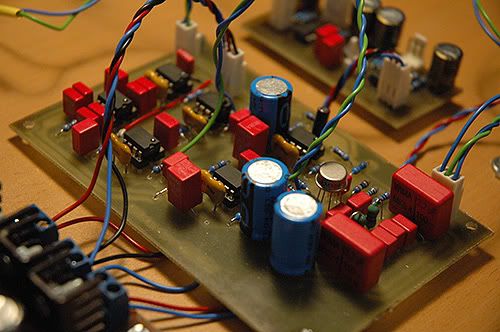
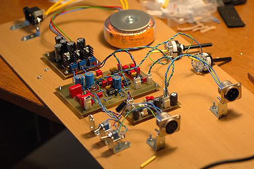
i've (almost) finished my 9k micpre..
it sounds ok, without noise, hum, ... etc
But haves problem with gain/attenuation!  :-\

I can't attenuate this thing enough, it goes to 0dBFS very easily! Even with max attenuation (2x 2k ohm)
Spoken word in front of ~15mV/Pa mic overloads my A/D when you speak just a bit louder. First I tried with two lorlin switches that give max 2 x 2k, then I put 2x10k pot instead to see what happens.. But still can't attenuate more than 25dB, even with 10k! Almost nothing happens when pot rises value from 2,5k to 10k. Don't have any idea where the problem is.

Help needed!
Where should I look for solution?  :'(

thanks!
 
What you need is a single two deck shorted switch. From memory, I'm going to say that one deck (the one closest to the input) was about 2.5k in total and the second was about 2k but it is about keeping the steps of the two stages in sync with each other.  I built this switch exactly as PRR laid it out in the following post and it worked out fine:

http://www.groupdiy.com/index.php?topic=4731.msg68601#msg68601
 
I'm not shure that will solve my problem, because there are people who finished 9k mic pre with 2 x 2,5k rev log pots.. So it is not about keeping it the way PRR sugested (not keeping linear resistance change between two gain stages). Let's say that pots are changing resistance in equal amount between two decks. There is a tolerance in pot, but we're talking about way things work now.
Anyway, dual pot works in this pre, so it's not about pot or switches it's about something else but have no clue what.. Hopefully someone will come up with some ideas.. ;)

thanks for reply
 
Doublecheck resistor values. Especialy R73, R109, R88, R115. If these were accidently fitted 10k instead of 1k it could have your described effect. Good luck.
 
Also chck this thread page no2,see the pic halfway down the page
http://www.groupdiy.com/index.php?topic=28684.20
On the schematic the pot wipers move up the diagram,which is clockwise for gain.
in fact decreasing resistance = increasing gain
you may be getting confused ?
 
Check your DC first.
Max attenuation is 2K5. People are using 2K2 pots because it's the only thing available, but it won't fully attenuate the circuit.
Anyway, to rule out your switches, pull them and put two resistors in their place to make it a fixed gain amp. Something around 1K5-2K should give you quite a bit less than max gain, so if you're still having problems, it's obviously something else. Good luck.
 
DC Voltages are perfect, checked that again

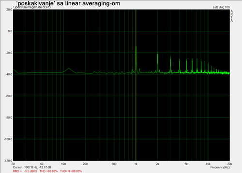
I wired two 2k35 resisors instead of switches/pots to measure the gain at that point of resistance. I got 40.15dB gain. Then I wired 10k dual log pot to see what happens, keeping eye on FFT and sinewave I sent. I noticed that when gain is more than ~48dB noise and THD starts to oscilate up down in ~20dB segments.

here is up down thing with linear averaging:
test01_posk.png


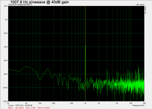
Then I put out servo (TL042, in my case NE5532), and resistors  R82, R118 i R119. to see what happens without servo, assuming there is a problem. But no.. same up-down happens at same gain. here is a measurement.. bit strange upper harmonic distortion. (this is at gain 40dB = stable)
test01.png


thank you everybody for replies
 
Hello all I've moved this question into the 9k thread instead of in it's own.

I built up my 8 channel rack this past summer and all but one channel work great!  I was hoping I could explain the problem and what I've done so far and maybe someone could point me in a direction that my brain won't go on it's own.

Ok here goes.

  When it was finished the channel was intermittent on output so I made sure that my output connection was not shorting out on anything and it wasn't.
  Then moved to make sure the input was not doing the same thing, and it wasn't.
  I then disconnected the channel from one side of the balancing board and connected it to the other side with the same result, NO OUTPUT!

  I have since removed the pre from the enclosure to be able to work on it easier.  I have checked all of the DC on all of the IC pins against a known working channel and they all correspond, give or take.

I have also gone as far as pulling some of the caps to make sure they were giving out their correct values and all have checked out so far.

I will say on my IC 29 & 22 on pins 2,3 I read an average of 12.36Vdc on both the good and bad channel where as the rest of the IC's read 0Vdc on the same pins.  This confuses me, and I'm sure if I knew slightly more than i did i would understand why.  If I need to post the amount of DC on my opamps I will.

Anyway, if you have a theory or suggestion I would greatly appreciate the help.

Oh, I don't have a scope, and apparently no one in this damn city has one, so I won't be able to do anything thing that requires one.

Thanks in advance,

Casey
(Signalflow)
 
This is a response to both signalflow and uncle:

In the four channels I built, I wound up with one bad 5534 chip.  I would try swapping those around.
 
Oh snap jdr! :eek: that is friggin awesome! 

I'll try switching out my chips as mushy suggested and if that doesn't do the job then I'll be building that handy signal tracer. 

I'll build one even if swapping solves the problem.......you never know.......

Thanks,

Casey
(signalflow)
 
Hi Everyone,

Does anyone have a parts list for the wima caps I cant seem to find them all at mouser. Im new at this, ur help would be greatly appreciated..........

Thx
 
Back
Top