SSL 9K Mic Pre

GroupDIY Audio Forum

Help Support GroupDIY Audio Forum:

This site may earn a commission from merchant affiliate links, including eBay, Amazon, and others.
[quote author="khstudio"]
I'm also drawing the frontplate of the original ssl9k 4 channel preamp.
I'd like to see that. What file format or program are you using for it & would you share the file?

& No... the link doesn't work.[/quote]

Pdf is okay bro
Greets
Rolo
 
Not here Bro. :?

It doesn't work, I keep getting this message:

Not Found
The requested document was not found on this server.


1st you say it doesn't work now you say it does... I don't get it.

Maybe the server it's on is going on & off line, I don't know.
 
[quote author="khstudio"]Not here Bro. :?

It doesn't work, I keep getting this message:

Not Found
The requested document was not found on this server.


1st you say it doesn't work now you say it does... I don't get it.

Maybe the server it's on is going on & off line, I don't know.[/quote]

No, i mean still dont work...
i tought you was the original poster of the file...but it was Neeno


i just sent him a PM... lets see if he can post that again
Rolo.
 
Hi there!
I don't what you're exactly looking for , but , have a look here :

http://www.beatbazar.com/guests/ssltech/
 
thank you for replies,

I can understand that TL052 is limited to +/- 15V so it's powered with lower voltage than NE5532
But don't know why NE5532 is powered by 18V when it can handle 24V, and MAT02/LM394 also?

I wonder can use +/- 24V?
I'm going to use 5 rails PSU, so i don't need to bother with diodes. Maybe that is the reason for 18V, so you can lower voltage to 15V with 3 rail PSU and two diodes?

tnx
 
[quote author="uncle"]But don't know why NE5532 is powered by 18V when it can handle 24V, [/quote]

FWIW, the 5532-datasheets I've seen all mention +/- 22V as abs. max. ... which of course doesn't mean 24 might go well for a while, bit still...

Bye,

Peter
 
[quote author="RedNoise"]Hi there!
I don't what you're exactly looking for , but , have a look here :

http://www.beatbazar.com/guests/ssltech/[/quote]

Cool....
looks thats the one
 
[quote author="uncle"]
But don't know why NE5532 is powered by 18V when it can handle 24V[/quote]

Do you mean the NE5534? There are no NE5532 on the schematic.


Casey
 
[quote author="signalflow"][quote author="uncle"]
But don't know why NE5532 is powered by 18V when it can handle 24V[/quote]

Do you mean the NE5534? There are no NE5532 on the schematic.


Casey[/quote]

NE5534 has +/- 20V as the max voltage on all of the datasheets I have.

Cheers,
Ruairi
 
the TI data sheet calls for +-22 but now it's splitting hairs. I'm more curious of why we're talking about 5532's instead of 5534's? Has anyone tried running at 20-22V on these? Is head room the only advantage?

Casey
 
you're right about NE553X voltage, I mixed something in my head.. aswell as speaking of NE5532 but think of NE5534. Sorry for that. :oops:

But for example, OPA604 and OPA2604 are listed as 24V MAX.. If I use them maybe I can go with 24V or 22V?
:razz:
 
[quote author="uncle"]But for example, OPA604 and OPA2604 are listed as 24V MAX.. If I use them maybe I can go with 24V or 22V?
:razz:[/quote]
Sounds like a question and the answer in the same sentence :wink:

But let's sanity-check, what are you expecting from releasing the max amount of Volts on these chips ? It might be time we try to get some sort of ranking over here... like: this mod will make a cat#1-type of difference in sound (say good song vs mediocre one)... or a cat#5-type of improvement (shutting up the neighbours when you're about to start recording....)

I figure 22 or 24 V is somewhere in cat#12... :cool:
 
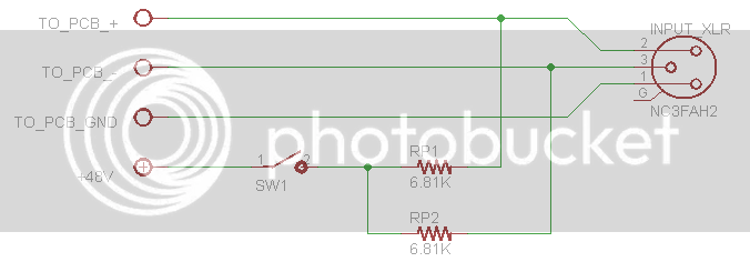
phantom.png


Rp1 and Rp2, are not on PCB, is this proper way to wire them?

what circut should I add for LED signalizing +48V ON/OFF?

tnx
uncle
 
[quote author="uncle"]
phantom.png


Rp1 and Rp2, are not on PCB, is this proper way to wire them?

what circut should I add for LED signalizing +48V ON/OFF?

tnx
uncle[/quote]

Looks right for the +48.
Basically run the LED the same way with a 3.9k resistor between it and the +48v.
 
[quote author="geoff004"][quote author="uncle"]
phantom.png


Rp1 and Rp2, are not on PCB, is this proper way to wire them?

what circut should I add for LED signalizing +48V ON/OFF?

tnx
uncle[/quote]

Looks right for the +48.
Basically run the LED the same way with a 3.9k resistor between it and the +48v.[/quote]
:shock:
Not advisable INMO
Use a seperate +ve supply(12v) for all led and (relay) suppliies,switched
by a seperate pole of a Double pole switch !
loading the phantom rail with LED's is a no,no !!
 
Along those same lines of Rp1 and Rp2 where the hell are Ra and Rb? Not on the board so they must be somewhere else.

Digi says the M7827-ND 15uH Inductors are obsolete. They only offer SMD replacements. Found them at Mouser.

Ken
 
is anyone running the Keith psu on a 30VCT transformer?
that gives a +41 as phantom... i'd like to reach 48V perfectly...

i know the formula 1.25 x (1 + (8k2 + 240 (/240)) = 48V but that gives me 41V...

Should i use a 10k trimmer over the fixed 8k2 resistor.

Thank you.
 
Back
Top