SSL Clone compressor ratio measurements

GroupDIY Audio Forum

Help Support GroupDIY Audio Forum:

This site may earn a commission from merchant affiliate links, including eBay, Amazon, and others.
My friend finished building my G-SSL clone and it is all ok except today I checked the ratios as described on here in another post. My ratios are measuring 1.52:1 at the 2:1 setting, 2.08:1 at the 4:1 setting and 2.78:1 at the 10:1 setting. These are way out so anyone know the problem. I'm not particulaly electronically minded but my friend doesn't have internet connection at the moment and I could pass this onto him when I next see him. Also he had a couple of DBX 220's lying around which he has used, they just say 220 nothing else ie 220b, 220c which I have heard bandied about on here. Cheers for any solutions in advance.
 
Hi,

i need some help !!!!!!!
I'm new to DIY project, i've bought 2 SSL clone compressor (one with VCA DBX2001 and the other with THAT and sidechain & Thrust mode) some times ago, and i had some problems with the unit with the DBX2001 (the other one work perfectly and is well calibrated). I didn't build these units, i just bought them ready to go. Now i'm decided to learn with this DIY project and understand some things so it will be possible for me to make the servicing myself...
Here is my problems... From what i remembered the comp with the DBX2001 worked perfectly at the begining, then i have some problems with the VCA, so i find a tech to change the VCA... Since it take some time to find some 2001 VCA to replace them, i find an other unit (the one with the THAT VCA and the sidechain), since i had repaired the other unit, i didn't use it because the new one had more options (sidechain & Thrust mode)...
But now i would like to use my unit with the 2001 VCA but it seem that it has some problems...

I tested the ratio measurements with the SSL TECH method and measure this:
@ ratio 2 ==> +2.2 db
@ ratio 4 ==> -1.3 db
@ ratio 10 ==> -3.5 db (it's somewhere around this value, i can't remember correctly...)


Is it possible that some ressistors could be dead after having my VCA troubles ? For exemple is it possible that a 1K resistor after having a problem , make only 500 ohms or less ?

I ask these questions because where there should have a 1k resistor (the one for ratio adjustements, at the bottom of the VCA beside the 1M resisitor, i think...), i can measure a value of 247 ohms (instead of 1K).

On the other side where there is the 27K resistor (at the top of the VCA), i can mesure a value of 28,9 K (right VCA) and 29,1 K (left VCA) instead of 27K.

It seem that there is some other resistors that have some difference with what it should be... I will make more measurements and let you know.

Let me know if you need more infos.

Thanks,

Lionel


Lionel,

Measuring resistors while they are in a circuit will never give you an accurate reading.  Unless they're burned, the resistors are fine.  The problem is that whoever built your gssl didn't calibrate it.
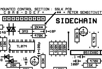
There is one resistor that controls the ratio calibration.  It's the 120K resistor in this photo:
meteradjust2Klayout.gif


Replace that 120K resistor with a 200K trimpot, and you'll be able to perfectly calibrate the ratios.
That's assuming that all the other components are the correct value.  It might be worth checking that since you didn't build it.
 
regularjohn said:
Measuring resistors while they are in a circuit will never give you an accurate reading.  Unless they're burned, the resistors are fine. 

Thanks for this important info !

regularjohn said:
The problem is that whoever built your gssl didn't calibrate it.
There is one resistor that controls the ratio calibration.  It's the 120K resistor in this photo:
meteradjust2Klayout.gif


Replace that 120K resistor with a 200K trimpot, and you'll be able to perfectly calibrate the ratios.
That's assuming that all the other components are the correct value.  It might be worth checking that since you didn't build it.


It seem that i have a 100K (since i have some DBX 2001 for the main VCA it should be ok from what i read on the PCB and shematic ?? Can you confirm that ? Thanks for the trick for the 200K trimpot, i will try this...

Here is some more infos : my main VCA are DBX 2001 and the other one is a THAT 2180LB

Is there some special modification to use the DBX 2001 or is exactly like the 202 ?

For the solo VCA (in the corner) is there some modification to do if i use a dbx 2150, THAT2180 or 2181 ?

If i remember SSL TECH speak about the 1K (increase this value will lower the Ratio) at the bottom of the VCA for RATIO adjustements what is the difference with the 120K modification ?

I have a look at the method for reading the resistor value (with the color bar code) so  have checked all the resistors everything seem to be ok except the resistors around the VCA the 27K for unity gain (mine seem to be 30K), and the 1K at the bottom of the VCA (mine seem to be 10K)

Here is some pictures let me know if i have read the correct value...

Thanks for your help.

Lionel


Attachments

  • SSL 127K - 100K for ratio calibration.jpg
    SSL 127K - 100K for ratio calibration.jpg
    269.7 KB
digiteck said:
I tested the ratio measurements with the SSL TECH method and measure this:
@ ratio 2 ==> +2.2 db
@ ratio 4 ==> -1.3 db
@ ratio 10 ==> -3.5 db (it's somewhere around this value, i can't remember correctly...)

Just to be clear these values are for a 10 db increase at the input...
 
According to THAT DN127 for a DBX2001 substitution (a DBX2001 is the only DBX Class A VCA), the wire links instead of the not fitted 1M resistors and the 50K trimmers seem missing in your pic. You might have fitted these from traceside, else  I'd complete the build first and measure ratio behaviour again for a more predictable result.
Resistor changes at VCA input from 27K to 13K and feedback resistors at current to voltage conversion NE5532 from 15K to 6K5 (this is 2x 13K in parallel) with 150pF instead of 100pF compensation cap across might help further.
For ratio adjustment see previous post from regularjohn with trimmer initial setting about centered.
 
Harpo said:
According to THAT DN127 for a DBX2001 substitution (a DBX2001 is the only DBX Class A VCA), the wire links instead of the not fitted 1M resistors and the 50K trimmers seem missing in your pic. You might have fitted these from traceside, else  I'd complete the build first and measure ratio behaviour again for a more predictable result.
Resistor changes at VCA input from 27K to 13K and feedback resistors at current to voltage conversion NE5532 from 15K to 6K5 (this is 2x 13K in parallel) with 150pF instead of 100pF compensation cap across might help further.
For ratio adjustment see previous post from regularjohn with trimmer initial setting about centered.

Hi Harpo,

you go a bit fast for me ! And my english is not so good... Let me know if i have understand correctly....
- i should put a wire link at the 1M resistor place (so 2 wire link since there is two 1M resistor, one for each VCA)
- add the 50K trimmers (two 50K trimmer, one for each VCA), since there is no place to fill them, how should i proeed ?
- change the 27K resistors (for unity gain) from 27K to 13K. it seem that i have a 30K (20K +10K in series) at the moment, can you confirm that (see the pictures)

And you said : "feedback resistors at current to voltage conversion NE5532 from 15K to 6K5 (this is 2x 13K in parallel) with 150pF instead of 100pF compensation cap across might help further"

On the schematic i can see four 5532, two with the 15K and the 100pF (the first just after the VCA) and two other with 10K and 100pF(the second just after the first 5532) but on the PCB layout i only see the two 5532 with the 15K and 100pF, it's on the side of the right VCA, it should be these that i have to change ?

Thanks,

Lionel
 
is there someone who could confirm the value i found for the 1K (VCA cv out, if i'm not wrong), 27K (for unity gain) and 127K (for correct ratio) resistors...
See the pictures...
For the 1K i found 10K
For the 27K i found 30K (20K + 10K i series)
For the 127K i found 100K (according to the original design with 202 VCA it should be ok but i will try the 200K trimpot...)

Thanks,

Lionel
 
and would like to have some answer to these questions :

For the solo VCA (in the corner) is there some modification to do if i use a dbx 2150, THAT2180 or 2181 ?

If i remember SSL TECH speak about the 1K (increase this value will lower the Ratio) at the bottom of the VCA for RATIO adjustements what is the difference with the 120K modification (or a 200K trimpot, regularjohn tip) ?


If you're using a 2180/2181 in the sidechain, remove the 47ohm resistor connected to pin 4 of the VCA.  Some people - including myself - also remove the 10K between pins 3 and 5.  This seems to keep the GR and output fairly even when switching between ratios.  With them both in there, like you've got, it seems that there's more GR and less output at 2:1 than at 10:1.

Also, the reason you see four 5532's in the schematic, is because the 5532 is a dual opamp (ie 2 amplifiers in one package).  Each amplifier is shown seperately on the schematic, even though it's only 2 physical opamps.

100K was the value, IIRC, for the dbx 2150 and possibly also the 202.  But using a 200K trimmer allows you to perfectly calibrate the ratios rather than just plopping a resistor in there and hoping it's correct.  But this resistor is the ratio calibration resistor.  It doesn't set the amount of difference between the ratios, if that makes sense.  It just moves them ALL up or down, so to speak.

Honestly I can't speak about the DBX2001's as I've never used them, and I'm not sure what modifications are necessary to make them work.
 
digiteck said:
Harpo said:
According to THAT DN127 for a DBX2001 substitution (a DBX2001 is the only DBX Class A VCA), the wire links instead of the not fitted 1M resistors and the 50K trimmers seem missing in your pic. You might have fitted these from traceside, else  I'd complete the build first and measure ratio behaviour again for a more predictable result.
Resistor changes at VCA input from 27K to 13K and feedback resistors at current to voltage conversion NE5532 from 15K to 6K5 (this is 2x 13K in parallel) with 150pF instead of 100pF compensation cap across might help further.
For ratio adjustment see previous post from regularjohn with trimmer initial setting about centered.

Hi Harpo,

you go a bit fast for me ! And my english is not so good... Let me know if i have understand correctly....
- i should put a wire link at the 1M resistor place (so 2 wire link since there is two 1M resistor, one for each VCA)
yes.

- add the 50K trimmers (two 50K trimmer, one for each VCA), since there is no place to fill them, how should i proeed ?
yes. Fitting these from traceside looks a little more comfortable to solder on. Trimmer initial setting centered = wiper about 0V.

- change the 27K resistors (for unity gain) from 27K to 13K. it seem that i have a 30K (20K +10K in series) at the moment, can you confirm that (see the pictures)
yes. The DBX2001 have different input current, compared to DBX202 or THAT218x.

And you said : "feedback resistors at current to voltage conversion NE5532 from 15K to 6K5 (this is 2x 13K in parallel) with 150pF instead of 100pF compensation cap across might help further"

On the schematic i can see four 5532, two with the 15K and the 100pF (the first just after the VCA) and two other with 10K and 100pF(the second just after the first 5532) but on the PCB layout i only see the two 5532 with the 15K and 100pF, it's on the side of the right VCA, it should be these that i have to change ?
yes. A NE5532 is a dual opamp. Changing these 15K resistors, located between label 'OUTPUT' and the NE5532s, changes the lpf frequency as well, so the 100pF compensation cap might better be increased to 150pF for rolloff @163kHz. (fitting 6K8 standard value resistors instead of 6K5 would increase output level by +0.4dB for GSSL in bypass condition, if this matters to you).

Your 10K resistors edit: seem to be 820Rs /edit, connected to the VCAs control port, should be replaced by their original value 1K. You might tweak these later on for same ratio behaviour between VCAs, if so required.
 
regularjohn said:
If you're using a 2180/2181 in the sidechain, remove the 47ohm resistor connected to pin 4 of the VCA.  Some people - including myself - also remove the 10K between pins 3 and 5.  This seems to keep the GR and output fairly even when switching between ratios.  With them both in there, like you've got, it seems that there's more GR and less output at 2:1 than at 10:1.

meteradjust2Klayout.gif


Just to be sure is it the first and the third resistors, those that are not on the picture just on the side of the VCA ? So it should be like your picture ?

100K was the value, IIRC, for the dbx 2150 and possibly also the 202.  But using a 200K trimmer allows you to perfectly calibrate the ratios rather than just plopping a resistor in there and hoping it's correct.  But this resistor is the ratio calibration resistor.  It doesn't set the amount of difference between the ratios, if that makes sense.  It just moves them ALL up or down, so to speak.

Yes that make sense, i understand ... So the 1K around the main VCA is only to adjust the differences between the differents ratios and the 100K for moves them all up or down.
 
yes. Fitting these from traceside looks a little more comfortable to solder on. Trimmer initial setting centered = wiper about 0V.

What doe it mean ? If i put out the VCA, then solder the 50K trimmer in place, it should be possible to put the VCA like before at the same place ?
And i should start with the trimmer at a middle position ? Is there a solution to adjust this if i didn't have an distortion analyzer (or something like this...) ?


yes. A NE5532 is a dual opamp. Changing these 15K resistors, located between label 'OUTPUT' and the NE5532s, changes the lpf frequency as well, so the 100pF compensation cap might better be increased to 150pF for rolloff @163kHz. (fitting 6K8 standard value resistors instead of 6K5 would increase output level by +0.4dB for GSSL in bypass condition, if this matters to you).

Thanks for the tips. Just to be sure is there only two 100pF compensation cap to change ?

Your 10K resistors, connected to the VCAs control port, should be replaced by their original value 1K. You might tweak these later on for same ratio behaviour between VCAs, if so required.

Ok.
 
I hate to reiterate this but I understand the thread is very long. Matt has kindly provided the components necessary for a GSSL to work correctly with different VCA's

http://diy.fischerworks.com/gssl_vca.shtml

Check this out first. Works for me. And WTF are you measuring ratios for??? Try measuring something after the knee kicks and you still have a crazy graph. Try using your ears.,

I use this on a drum buss. And sounds awesome. You using it on the 2 Buss? I have noticed the caps change the sound of the board by A lot.

John
 
digiteck said:
Just to be sure is it the first and the third resistors, those that are not on the picture just on the side of the VCA ? So it should be like your picture ?

Yes

Stagefright13 said:
http://diy.fischerworks.com/gssl_vca.shtml
Check this out first. Works for me. And WTF are you measuring ratios for???

Yes, I'm aware of that link.  There's also Martin's as well: http://homepage.mac.com/marten.thielges/gssl/calibration.html
However both of those links focus mainly on the THAT vca's, and neither make mention of the 202 or 2001 vca's, the latter of which are what are in digitek's comp.  So that link isn't really helpful here.

I can't speak for others, but I measure the ratios so I know the thing is working correctly.  Seems pretty basic that you'd want the controls to actually do what they're supposed to.
 
digiteck said:
yes. Fitting these from traceside looks a little more comfortable to solder on. Trimmer initial setting centered = wiper about 0V.

What doe it mean ? If i put out the VCA, then solder the 50K trimmer in place, it should be possible to put the VCA like before at the same place ?
And i should start with the trimmer at a middle position ? Is there a solution to adjust this if i didn't have an distortion analyzer (or something like this...) ?
With the part size of a trimmer between VCAs I doubt you can put your VCAs back in like before. Fitting some Milmax sockets or alike for this pin diameter to rise the VCA above the pcb might do the trick. Sockets are not needed, if you place the trimmers from traceside, obviously with the drawback of easy accessibility.

Just to be sure is there only two 100pF compensation cap to change ?
Seems so. If you change a parts value that is part of a R/C circuit, this will change frequency response. Check if it matters. You do the math. f=1/(2+PI()*R*C). The 22uF caps value at the output of the debalancing stage should still fit. The change from 27K to 13K in front of the audio-VCA with 47K in parallel at the sidechain summing node rises this HPF from 0.42Hz to 0.71Hz. I wouldn't care, but YMMV.

Your 10K resistors, connected to the VCAs control port, should be replaced by their original value 1K. You might tweak these later on for same ratio behaviour between VCAs, if so required.

Ok.
You seem to have read its value backwards. Looks like a 820R, not 10K.
 
Stagefright13 said:
I hate to reiterate this but I understand the thread is very long. Matt has kindly provided the components necessary for a GSSL to work correctly with different VCA's

http://diy.fischerworks.com/gssl_vca.shtml


Hello John,

i have seen Matt, Martin and Gyraf's website but like RegularJohn said there is no infos concerning the DBX2001 modifications (only for the THAT VCA).
And like i said i begin in DIY project and electronic so i need some help, i start from zero... but really want to learn and understand what i do.

Check this out first. Works for me. And WTF are you measuring ratios for??? Try measuring something after the knee kicks and you still have a crazy graph. Try using your ears.,

It was my ears that said there was something wrong... It make sense to have a correct ratio (minus very small differences), If i want something no too hard, i will not choose a 10 ratio but probably 2 or 4. I agree it could be great to have different value from the original design but what i want is the classics ratios...

I use this on a drum buss. And sounds awesome. You using it on the 2 Buss?

I'm also use it (my second SSL clone the one with the sidechain filter and thrust mode... the one that work great for the moment) for drum buss and mix buss. Depending on the source it's great on the mix buss. I mainly do mixing and mastering http://www.lestudio13.com

I have noticed the caps change the sound of the board by A lot.
So do you think it is better or just different ?
Maybe these changes are better for the DBX2001 ? Harpo any answer to that question ?

Lionel
 

Latest posts

Back
Top