Started my poctop D49c build!!!

GroupDIY Audio Forum

Help Support GroupDIY Audio Forum:

This site may earn a commission from merchant affiliate links, including eBay, Amazon, and others.

achase4u

Well-known member
Joined
May 1, 2016
Messages
85
So, I am hoping that reporting here might help others and perhaps even inform a guide if it is to be made eventually because  I am more of an electronics novice(but a good builder and solderer).  Here is the first board.  I am awaiting my tube now for installation.  That is one thing I am uncertain of.  The original m49 schematic shows the ac701 of course, which doesn't have the same pin-out as the JAN 5840.  Looking at the existing build pics, it is slightly hard to make out which leads are touching and not touching.  However, logic tells me that if they aren't going to the same PCB point, they shouldn't touch.

Here is my first pic.  Huzzah!

I plan on using Dany's D7 capsule.
 

Attachments

  • D49c board.jpg
    D49c board.jpg
    1.8 MB
Pip said:
5 and 7 go to same place no others should touch. Read the build thread thoroughly it's all there.

Thank you very much for clarifying the tube pins for me.

Which build thread???  There are multiple.  The one pertaining exactly to my round body version makes no mention of that.  The info isn't exactly organized, and it takes some looking to find the round body thread, because the original thread's link to the round body build thread takes you to an error page.

I see it now on just the original square version page.  I very explicitly follow directions, so I didn't think this other version would pertain to my build since there was an entire other build thread dedicated to the round puck version.
 
http://groupdiy.com/index.php?topic=51862.0

Really scroll down and read and search it it is all there.

There are pix of my build in there as well!
 
I gived you twice link for my schematic where's proper pinout for this circuit with 5840...
Here's pinout of the tube (bottom view)
http://www.r-type.org/pdfs/5840.pdf

5 and 7 goes together for plate.
2, 4, 8 are connected inside and you can use only one and cut the rest or twist them together (start 1-2mm from the glass).

How's with peluso - did you give up?
 
ln76d said:
I gived you twice link for my schematic where's proper pinout for this circuit with 5840...
Here's pinout of the tube (bottom view)
http://www.r-type.org/pdfs/5840.pdf

5 and 7 goes together for plate.
2, 4, 8 are connected inside and you can use only one and cut the rest or twist them together (start 1-2mm from the glass).

How's with peluso - did you give up?

Howdy!  Yes that's true.  Sorry, I thought it was modded somehow that was different to Dany's circuit because I didn't look closely enough.

Nope, didn't give up on it.  I need to get parts.  It's also being used for recording currently so I need to wait until down time.
 
5 and 7 goes together for plate.
2, 4, 8 are connected inside and you can use only one and cut the rest or twist them together (start 1-2mm from the glass).

yes indeed ,

I added the information about the tube connection in the the main thread as it was not there ,
thanks for catching this, 
Thanks for the thread ,  :)

Best,
Dan,
 
achase4u said:
ln76d said:
I gived you twice link for my schematic where's proper pinout for this circuit with 5840...
Here's pinout of the tube (bottom view)
http://www.r-type.org/pdfs/5840.pdf

5 and 7 goes together for plate.
2, 4, 8 are connected inside and you can use only one and cut the rest or twist them together (start 1-2mm from the glass).

How's with peluso - did you give up?

Howdy!  Yes that's true.  Sorry, I thought it was modded somehow that was different to Dany's circuit because I didn't look closely enough.

Nope, didn't give up on it.  I need to get parts.  It's also being used for recording currently so I need to wait until down time.

Great :)

Circuit practically is the same - and if you are going for C version (to be honest for A and B also but i didn't measured for it)  change cathode resistor value to be close as possible to the M49 circuit specs. For C also i recommend not using low pass filter and change output capacitor for 0.5uF.
 
poctop said:
5 and 7 goes together for plate.
2, 4, 8 are connected inside and you can use only one and cut the rest or twist them together (start 1-2mm from the glass).

yes indeed ,

I added the information about the tube connection in the the main thread as it was not there ,
thanks for catching this, 
Thanks for the thread ,  :)

Best,
Dan,

Thank you, Dan!  And thanks to everyone here at the forum.  I'm happy to learn these things with your help, and enjoy microphones I make with your parts!
 
Dan - question for you :)

How is connected input in your circuit?
Did you make switchable option for cardioid only - according to original schematic C1 via S2?
 
I tried looking through the build page - but didn't see mention of connections.  I see that the PSU kit comes with a 7 pin XLR.  Though I want to use a binder type.  I assume its fine to just substitute in a binder?
 
ln76d said:
Dan - question for you :)

How is connected input in your circuit?
Did you make switchable option for cardioid only - according to original schematic C1 via S2?

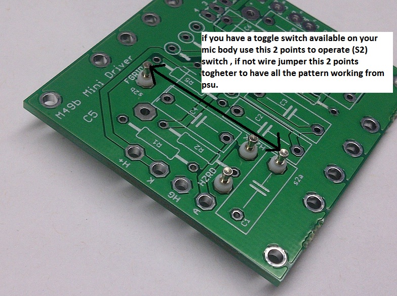
Input straight from tube grid and floating Fgrid capsule connection point ,

connect floating switch to those 2 points,  same points available on this round version as well,

Note:  To Operate S2 Cardiod only Switch
58d02819948cf.jpg


PSU board and TX board coming along...  I hear though that the classic series BV11r is better?  Hmmm.  No one really says how it is better...
 

Attachments

  • PSU board.jpg
    PSU board.jpg
    70.4 KB
achase4u said:
PSU board and TX board coming along...  I hear though that the classic series BV11r is better?  Hmmm.  No one really says how it is better...

BV11A - Direct replacement for M49/50, historically correct

BV11R - BV11A with extended low and low-mid frequency response - EC92, EF732, 5840, 6072a and 12AY7WA


If you truly need to spend more money for AMI stuff i would make investment in BV11A not R.
Divide all this AMI information by two.
Direct replacement was from Berlin not from Gaylord.
I would not want to use any transformer with  "extended low and low-mid frequency response".
It was made because Oliver used 5840/EF732 with original circuit values of electronic components, sometimes with realy minor (in my opinion not worth) modifications.
What i stated before - cathode resistor value change will give you better performance and closer to the original with AC701k.
Don't use LPF HPF, use C4 8-8.2pF capacitor and all should be fine.
Try to not using 1G resistors but some much more close to the original values.
I would use S2 switch inside the microphone body for cardioid only.
I'm not sure how pattern switching works in Dan version but if i'm right and for cardioid (with PSU switching only)  signal is going thru C1 1nF - you will get worse sensitivity and worse sounding microphone.
Not without a reason Neumann made optional switching with S2 for cardioid.
 
Here you have, for direct comparison with original schematic, this what am talking about!
Connection included ;)
 

Attachments

  • M49C EF732 without LPF.png
    M49C EF732 without LPF.png
    267 KB
Back
Top