Starting a modular console - CAPI/GDIY 508 rack build

GroupDIY Audio Forum

Help Support GroupDIY Audio Forum:

This site may earn a commission from merchant affiliate links, including eBay, Amazon, and others.
Parts have been coming in...

I've been slacking on transferring schematic to pcb layout. I learned KiCad the half-ass way, one step at a time. Figuring out the schematic part was a lot of work... Turning that into a pcb layout is a lot more. Hence the slacking. I appreciate the checkup, helps me stay on target. That will be this weekends project.

Since my brain needs an avenue to fill that slacking, said avenue has been eq's. I built a pair of the studer 169's, easy build, sound classy to my ears. I've also been slowly gathering parts for a pair of He69's.(Why are there so many 69's with eqs?)  Then, on a whim, decided I was going to try and wind some toroid inductors for a pair of 553 clones, so ordered some stuff from Nebraska Surplus.

Clearly time I could have spent figuring out the pcb layout. Time to refocus.

 
Time for an actual update.

I'm pretty much decided on a slight redesign of the fader channels.  In the spirit of keeping it simple, I think it's best to use the resources that those much more suited to audio circuit design than myself can provide.  Jeff's recently released two stage line amp board (2S-LA) takes so much work out of the pcb design process, leaving me with a couple of much simpler boards to design.

The Classic API 2S-LA:  http://classicapi.com/catalog/product_info.php?cPath=22_191&products_id=438 

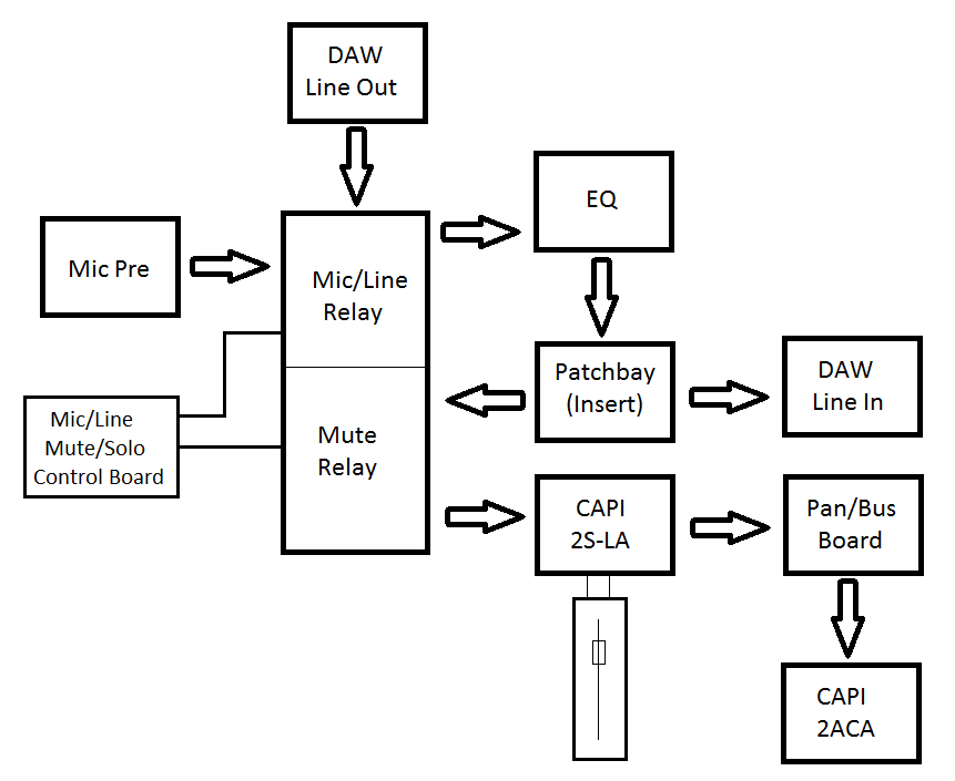
My new signal flow diagram.


I want to make a total of 3 small utility PCB's to complement the 2S-LA and achieve my desired goals:

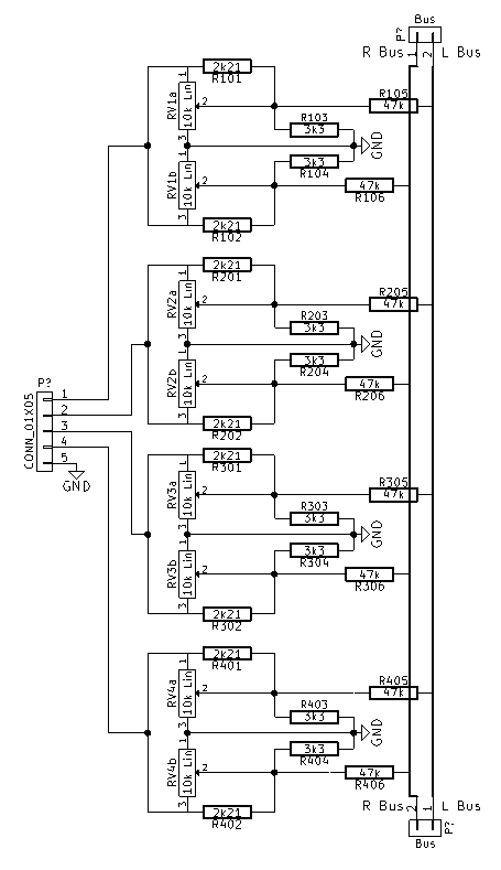
1) Pan and Stereo bus board, fed from the 2nd stage of the 2S-LA, dual linear 10k pot based on a schematic posted in the CAPI white market thread, 47k bus resistors, stereo bus.
2) Routing "Motherboard": the big rectangle in the middle of the picture.  Each of the large arrows represents a physical connection, most likely 3-pin .156" headers, and the CAPI plugin relay boards for each of the functions.
3) A control board for the Mic/Line and Mute relays on the routing motherboard.

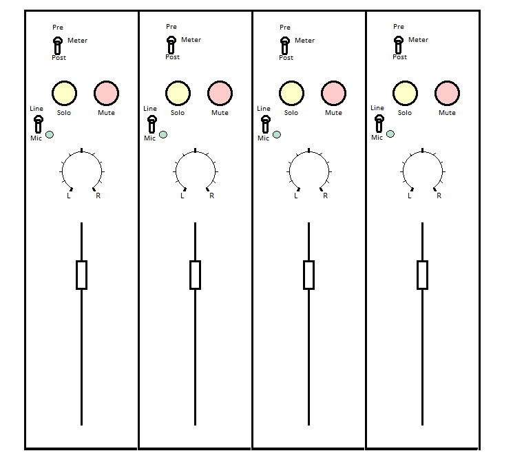
I have put together schematics for 1 & 3, haven't gotten to 2 yet, but it should be fairly simple.  1 & 3 are what matter for getting the faceplate layout and moving forward with the physical frame.  Speaking of which, updated panel layout:


1) Pan and Stereo bus board

The schematic I based this on is on page 40 of Classic API's white market thread.


Taking the unbalanced feeds of the 2nd stage and a ground connection from the 2S-LA's for the 5 pin in connector.  Kinda just took a stab at that one, if there's a better way to run the inputs, let me know.

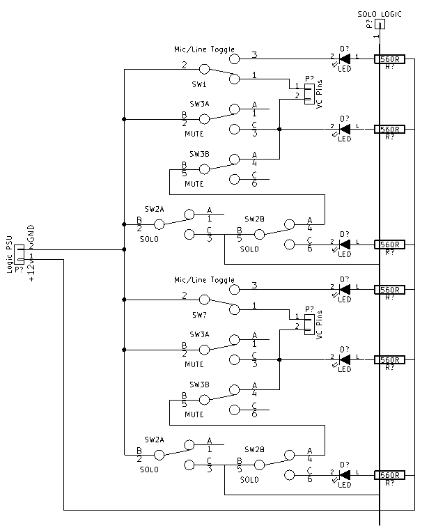
3) Routing Control Board

Showing 2 channels and solo logic bus:


This board gets a feed from a 12v logic PSU, probably multed from the Motherboard.  It's entire purpose is to control the vc pin connection to ground on the Mic/Line and Mute CAPI plugin relays located on the routing motherboard.  And light up all cool lookin' too.

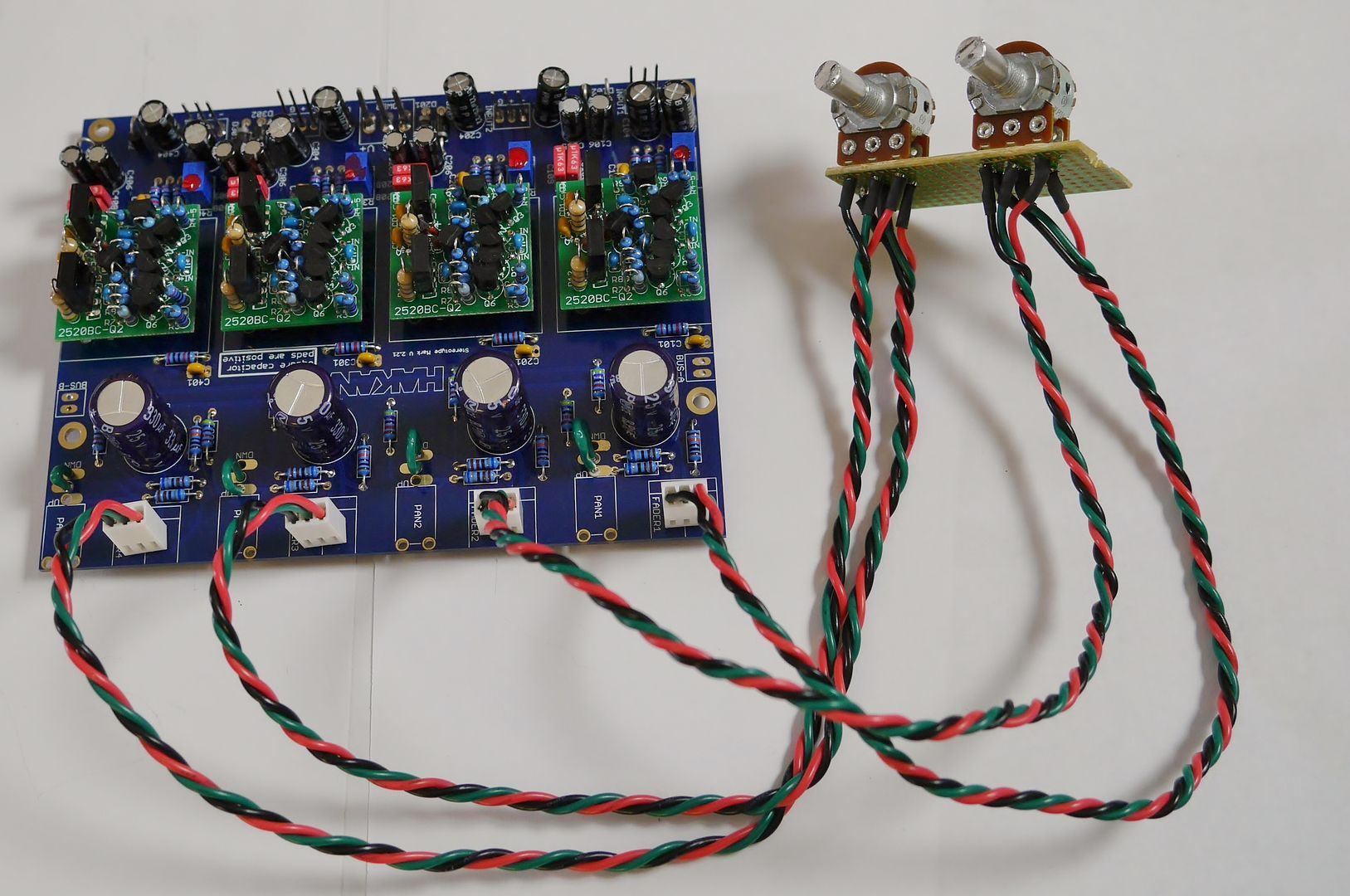
I still plan to use the hakanai stereotype boards for the 12 channels of line in.  I've got a layout pretty much done for a double wide 500 series faceplate with controls for the 4 mono+pan and 4 stereo.  I'll post some pictures of that in the next day or so. 

Thoughts before I start trying to turn these schematics into pcb layouts?

 
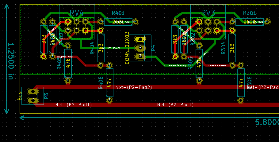
The learning process from schematic to pcb layout has taken all weekend.  I have something that might resemble the pan and bus board.  Pics below.  I'll post more info about this tomorrow, but for now, I just need to get the hell away from this... I have no idea what happened to the last 12 hours.  I had other stuff to do today...

I don't know why I stopped the ground plane where I did, but any input is much appreciated:


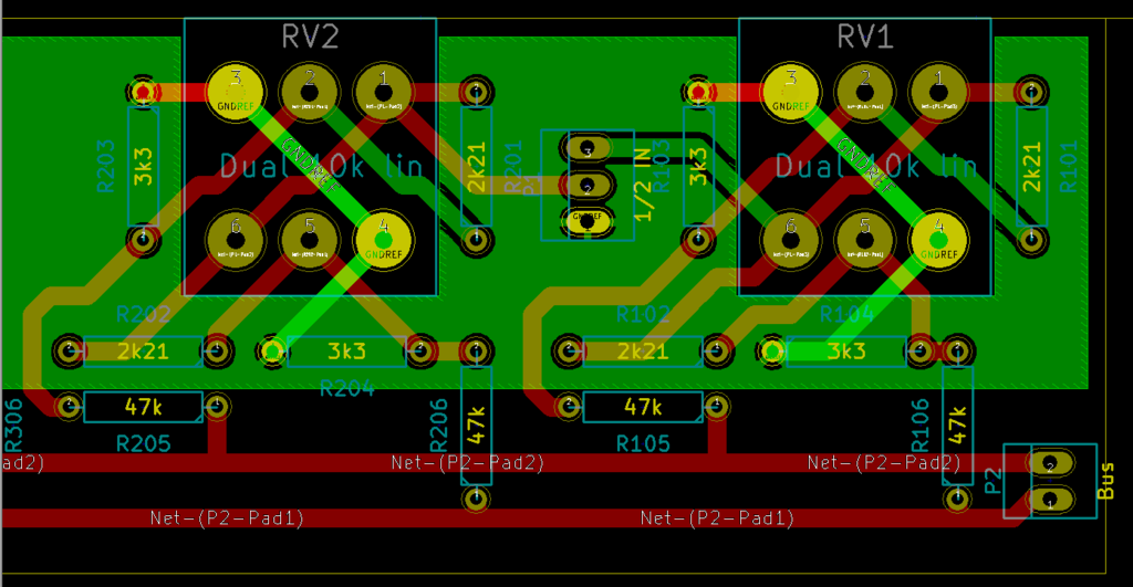
Closer view of 2 channels:


I'm sure there's errors, but right now, I don't really care.  I have a nice feeling of accomplishment.

Please point the errors out, though.

 
Not sure where I'll get the pan/bus boards made. Anyone have suggestions on a pcb manufacturer for very small runs?
 
I have dual 10k linear pot stock here with a center detent. I need to get them listed at the store. They are the P09 9mm series from BI. They feel great and are cost affordable.
 
Yes, please list them! The only options I was coming up with are the omeg pots from AML, but I am not a big fan of the 4mm shaft size on those... Doesn't jive with the API knobs.
 
Well, these are a 6mm shaft which I am not a huge fan of but I do have clear anodized knobs in stock that fit them. I also have a dual concentric pot that is dual 10k lin with detent on the outer shaft and a single 1k log on the inner shaft.

I guess I am way behind on things!  :eek:
 
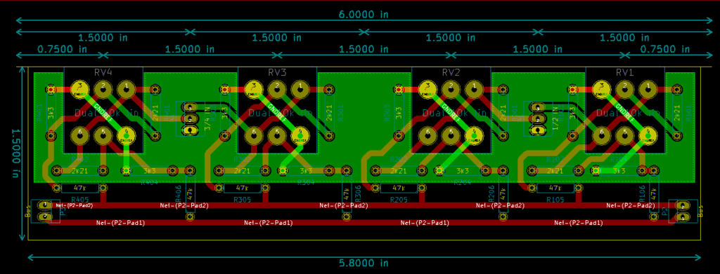
I've updated the Pan/Bus board layout for the BI dual 10k linear pots that Jeff is now selling. 

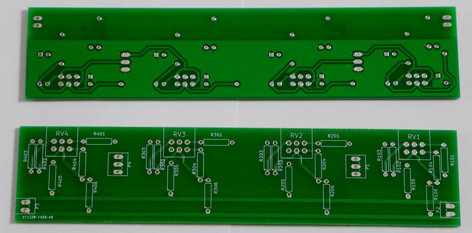
What I've ended up with is a 5.8" x 1.25" pcb.


Here's a closer look without the ground plane pour filled in:


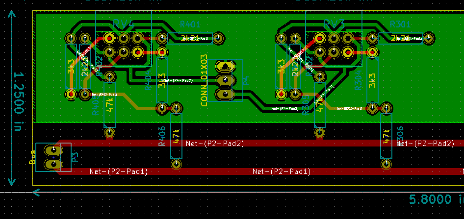
And with the fill:


I decided to keep the ground plane away from the bus traces.  I don't know if it matters, I just wanted to keep any possible interference away from the main bus.  I have no logical reasoning to back that up.  If you wouldn't mind giving the layout a once-over and point out any noobie mistakes, I would much appreciate. 

USPS just delivered my usually-bi-weekly-at-this-point CAPI order, a whole bunch of the 2S-LA boards, the pan pots, some more metalwork and parts to finish up another 8 slot bucket, and I figured I needed another pair of vp26's.  I took a sanity day off work tomorrow, so I'm pretty excited to put in some quality time with the soldering iron.  Maybe start working on another batch of gar2520's... I had a marathon couple of weeks churning those out, but then needed to take an extended break.  Stuffing those will start to make you go loopy after a while.
 
It's a crappy, rainy weekend in the midwest US, but thankfully it's allotting me a little precious free time for some further console work.  Most of my weekend free time recently has been devoted to yard work and trying to tame the lawn, thanks to the usual springtime rain-sun-rain-sun cycle.  Weekday free time has been eaten up by varying crises at work... it's nice to finally get a soldering iron in my hand and get some progress made.

I'm ordering a batch of prototype PCB's for the pan/bus board today.  I've decided to go with pcbcart.com per Gary's suggestion.  The pricing and turnaround seem pretty darn good for a small batch run.  Fingers crossed I got everything correct in the layout and Gerber file production, but the only way to know for sure is to order some up and try 'em out.

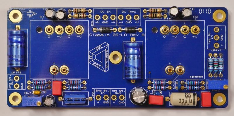
I've built up a few of the CAPI 2S-LA dual stage line amp boards to start testing the fader channels that will feed the pan/bus board into the 2ACA board.  Here's a pic of a stuffed board (minus DOA's) for reference:


The board is simple enough.  First stage is a DOA balanced, transformerless line receiver, which will feed one of the Alps 10k faders I got from AML.  Wiper of fader goes to 2nd stage booster amp, which will control the amount of gain at hand in the fader.  Output of 2nd stage feeds the pan/bus board.

I've wired up two boards and done the CMRR calibration.  It's a pretty simple process.  I wired up a cable per Jeff's instructions to feed the 1st stage input with a Pro Tools signal generator at 400hz from a digi 003 output. The first stage output (unbalanced) goes back to a digi 003 input, leaving the (-) end of the input cable floating.  There's a free Bomb Factory noise meter plugin that comes with Pro Tools, so I used that to monitor the input signal.  Adjust the first stage's trimmer resistor to minimize the level shown on the noise meter plug, drop a dab of nail polish on the trimmer to hold it in place, and done. 

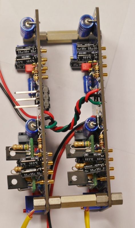
I played around with some standoffs I had on hand to try and figure out how I'm going to physically orient everything.  This is what I've come up with (obviously I'll get some proper sized standoffs instead of rigging a bunch together):


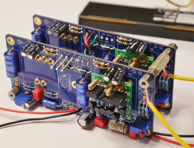
Worked out to be approximately the correct spacing for 500 series.  For power distro, there's a DC in and a DC through on each board, so I figure I'll just daisy chain them all together as shown in the pic above, using shorter wire.

Here's another angle:


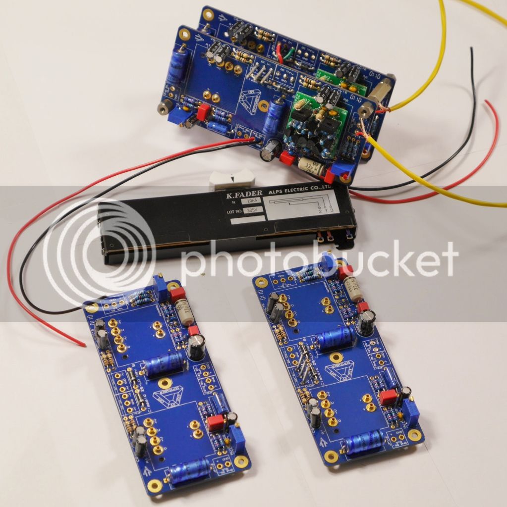
And since I had the camera out and was having some fun, a family shot:


Next step will be to wire up faders to my 2 channel frankenstein rig and start playing around with the 2nd stage gain staging adjustment.  I have a few thoughts/questions in my head that I will post a little later on today.  For now though, just some pics.
 
Fader Calibration

I'm starting to feel like I've thought myself around in circles about this, so best to post it up for feedback.

The 2S-LA 1st stage unbalances, so -6db.  Signal goes to fader, wiper to 2nd stage input.  Info Jeff has provided says that the 2nd stage would usually provide +6db of gain, and I'm assuming this is with fader wide open.  Another +6db if the 2nd stage output goes directly to a 1:2 transformer, or +6db made up through bus resistors and the first stage of the 2ACA board. Seems easy enough.

So my thought currently is to calibrate the faders so that line out level of DAW signal generator = +6 line in level from 2nd stage of 2S-LA.  Or should line out = line in?  I've provided my two lines off thinking below (I find it more useful to provide my step by step line of thinking so flaws in my logic can be highlighted), please point out which logic is correct.

1) line out = +6 line in: So the line out gets unbalanced by first stage of 2S-LA, which is -6db.  Goes out to Fader, then to 2nd stage, where with fader wide open would provide +6db.  That would put it back at unity.  However, the whole unbalanced/balanced/-6db thing has me thinking, an unbalanced in to DAW would read as -6db vs. an equivalent balanced in.

2) line out = line in: Same thought train as above, screech on the brakes at "However, ".

So that will help me understand how to calibrate one channel.  The next divergent thought process is: how to calibrate multiple channels?  Same format as above:

1) Calibrate all to level determined in above question:  Seems the most straight forward, every channel would be equal when fully open.

2) Calibrate all to unity, either 0db or -6db (again, depending on level determined in above question) to align with first fader: So, I have 10% tolerance faders.  In theory, each channel will have a different unity gain point (if I calibrate all with first option).  I'm thinking that matching fader location of unity gain points might be the better way to go.  Yes, there might be slight variations in full open gain, but there would be consistent unity across all, and that seems more valuable than max gain full open.  This could, however, be a huge pain in the ass, as I am just theorizing and haven't learned or considered what it would take to actually match consistent unity positions across all faders... or if it's even worth it.

Thoughts?
 
It's all starting to come together...

It's been a little over a month since I updated, and I'm really happy with the progress.  I've gotten to the point where I can now envision this whole hair brained scheme actually working! 

First up, I've decided to pass on the mute/solo functionality for the time being.  This will be part of the Mark II version.  The reality of the complexity and amount of work this project entails has finally caught up with my desire for features, and the mute/solo would end up adding at least another month before I start tying all the pieces together into one cohesive unit. 

Now, the actual progress:

Pan and Bus board

I finally got around to having these made based on the pcb layout I posted earlier in this thread.  The schematic is copied directly from one Jeff has on his site (http://www.classicapi.com/catalog/images/gallery/pots/BI/Passive-pan-pot-network.pdf), using BI dual 10k linear pots with center detent.  I had the boards made by pcbcart.com on advice from Gary, using their prototyping service.  They're very basic boards, aren't laid out very well, they probably have problems I'm unaware of, and are based solely on a schematic I copied from someone else, but I'm really proud of them.  I never would've thought even 6 months ago that I could design a pcb.


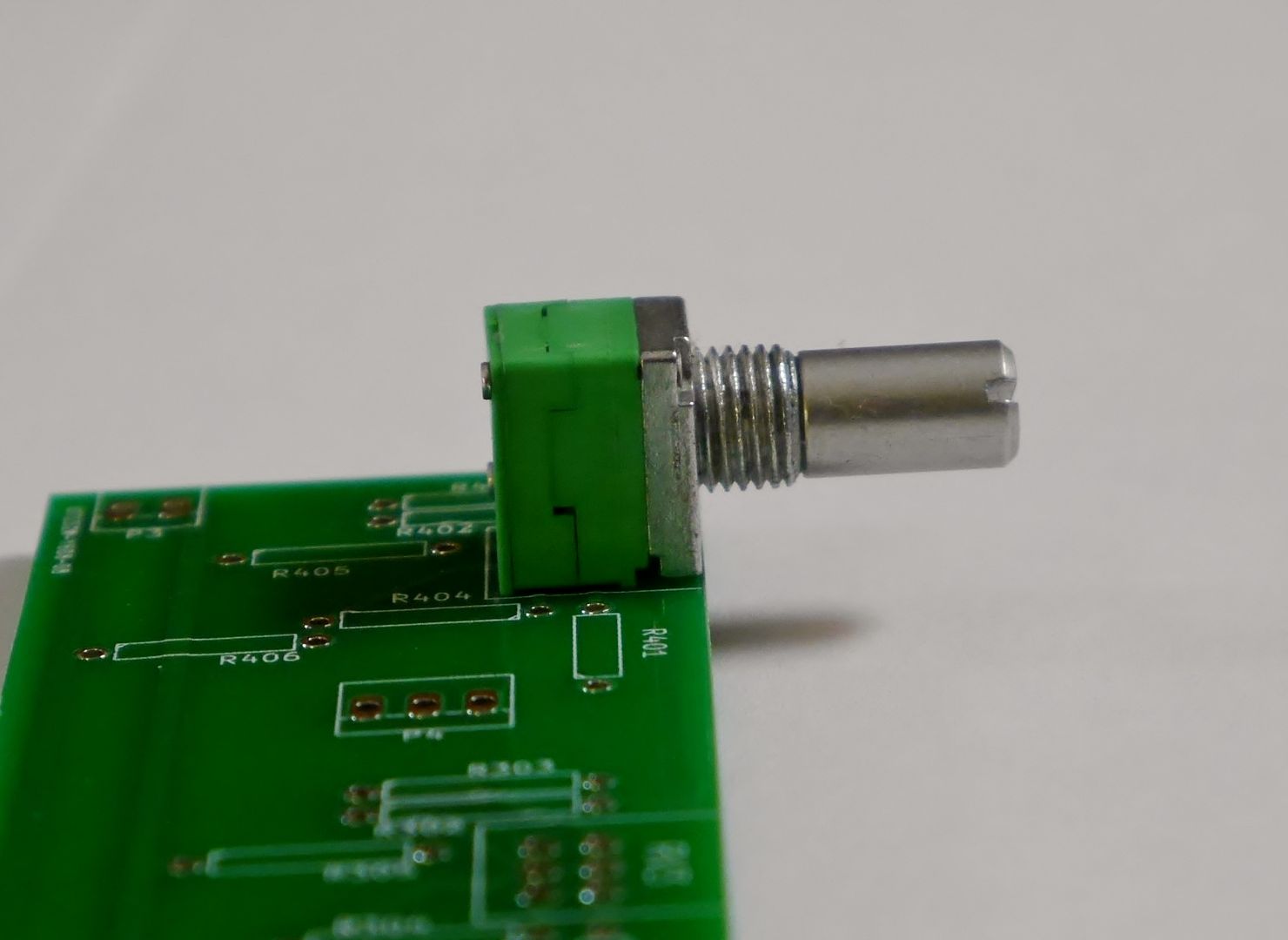
My main concern was getting the actual fit right, as I want the pan pots to sit flush with the front of the board.  I'm happy to report that it was a success!


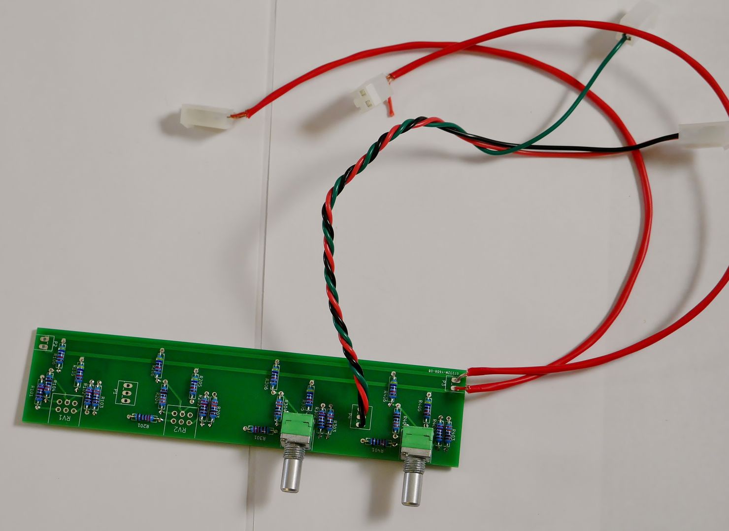
So, the pots fit, but do the boards actually work?  With some nervousness but mostly overwhelming excitement, I wired up a test board:


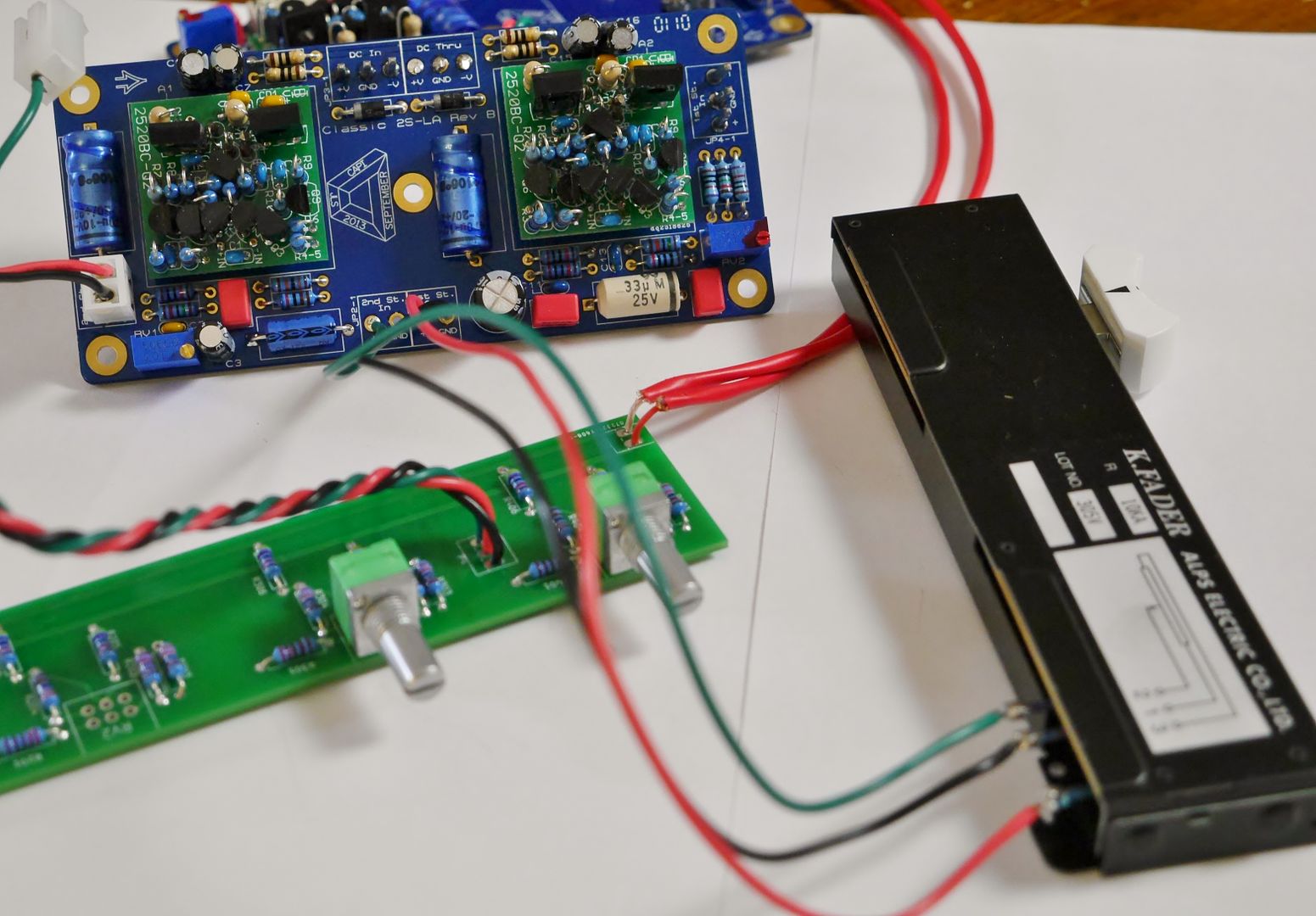
And hooked it up to one of the 2S-LA channel boards:


AND IT WORKED!!!!!  Oh, joyous day!

I tested DAW out > 2S-LA 1st stage > alps 10k fader > 2S-LA second stage > pan/bus board > 2ACA (ACA side only) > DAW in using test tones.  The pan law seemed very natural throughout the full L to R sweep, and center detented position was showing both L and R sides of a stereo track equal in the DAW in.  After months of building individual parts of the chain and plotting how they will work together, I am so, so happy to have a successful test of everything together!!

I'll make another, much more lengthy post later on today to discuss the levels I'm seeing, how I've calibrated the 2S-LA 2nd stage and fader, etc...  I need to get all my notes together before I do that.

Stereo Line In's

I also successfully tested the hakanai Stereotype boards that I will be using for stereo line ins to the mix bus. 


I picked up some dual 1k log pots from JLM audio and, while the L/R tracking is not 100% throughout the range of the pot, it's close enough for me.  The L/R balance is flat when the pots are wide open, so worst case scenario I can leave them wide open and control the level coming out of the DAW if I find the L/R matching to be too problematic.

Anyways, pics for now, more detailed technical stuff later.  I'm super excited that this whole project is starting to become more reality than concept. 
 
First off, the testing setup.  I've probably provided far too much detail, but I figure the more detail the better.

DAW: Pro Tools 9
Interface: Antelope Orion 32
Signal Generator: Pro Tools signal generator, 1Khz sine wave measuring at -20db
Metering: TL master meter (free plug w/ Pro Tools)
Connections: All Shielded Balanced Mogami cable; DB25 connectors @ Orion 32; .156 Molex on PCB's
                            Orion 32 line out to 2S-LA 1st stage in; +/-/shield connected on both ends

To set the gain of the 2nd stage, I sent the -20db test tone balanced out of DAW to balanced in of 1st stage.  Fader connected to 2S-LA with 1st stage + output to 3, ground to 1, and 2nd stage input being fed by the wiper.  The 2nd stage output was feeding a DAW balanced line in, with only the + connected on the 2S-LA output (-/shield floating), +/-/shield @ DAW input on DB25's.  The interface and Pro Tools didn't put up any fuss with this arrangement, so it seems to have worked.

With the fader wide open, initial levels @ DAW line in were around -16db, so if my math is correct, the 2nd stage was providing around 10db of gain (1st stage is -6db).  I adjusted the 2nd stage trim pot until the meter was reading -14db, thus providing the full 12db of gain expected from the 2nd stage. 

I then connected the 2S-LA second stage output to the pan/bus test board, +/gnd with standard hookup wire.  Bus outputs are wired with the mogami shielded stuff, a seperate wire for left and right, with -/shield floating @ bus board, +/shield connected at 2ACA L/R inputs.  See pics in previous post. Balanced outputs of the ACA's 2623 transformers are connected with shield floating on the 2ACA side, connected at the DB25 on the Orion inputs.  Note: The booster stage of the 2ACA board is not being used.

I kept the fader wide open and fed the same -20db  mono test tone, coming back to a stereo track in pro tools from the L/R ACA outputs.

Meter readings:

Panned center:  -16.99db (let's just call it -17, but it was very consistent at the -16.99)
Panned Left: -11.9db
Panned Right: -11.95db  (let's just call them both -12db)

In the build notes on the 2ACA, it says that with a -2dBu signal through a 47k bus resistor, the output level of the ACA will be approximately -0.5dBu.  I still don't have a full understanding of dB, dBu, and dBV yet, but my logic is thus:

The ACA would provide approx. 1.5dB of gain, with the delta of -2dBu and -0.5dBu.  Fully panned to either side, I'm at -12dB from a -14dB signal (measured from the 2nd stage 2S-LA output), or approx. 2dB of gain through the ACA circuitry.  Seems legit.

Center panned, I'm at -17dB, so approx. -5dB from hard panned.  Jeff's panning schematic says it will give approx. -4.25dB pan law at center.  Given the rather mediocre testing setup I'm using, I figure the -5dB I'm seeing is close enough.  It sounds very natural throughout the panning spectrum thus far. 

Unless my logic is totally off, everything seems to be working as it should.  However, I would appreciate if someone could confirm or deny that!

Thanks,

Keith 


You know, it's a lot easier to sit over a soldering iron, in front of a computer, etc... during the winter.  The summer has definitely slowed progress.  However, I really need to get everything into a home.  I've been putting off designing a front panel for the faders, pan, and mic/line switch for a while; I've only ever modified .fpd files I've downloaded from other people smarter than I, and I know nothing about screw sizes, hole diameters, contersinks, machining, anything related. 

But, not wanting to start stalling out on the project, I decided a 90+ degree day > monsoon-style rainstorm (edit: that kinda sounds like an early 90's Phish setlist reference) offered proper motivation.  Turns out it's really easy to find all the information you need (so, Google exists...), FrontPanel Designer is stupid easy if you actually think about it logically and try, and I really need to stop putting things off.

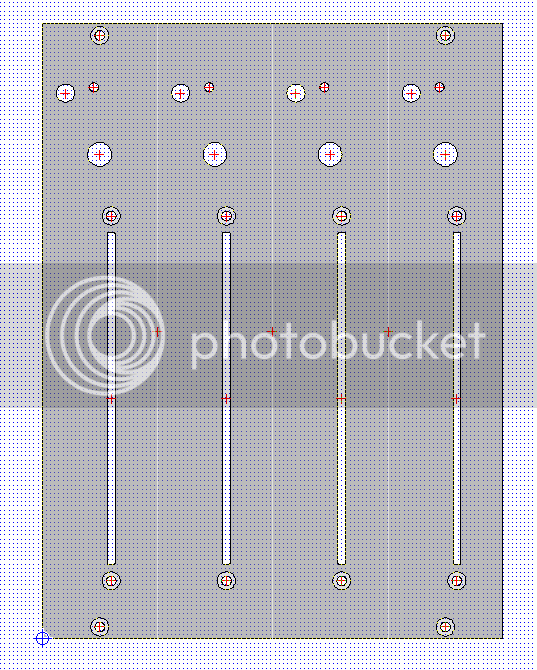
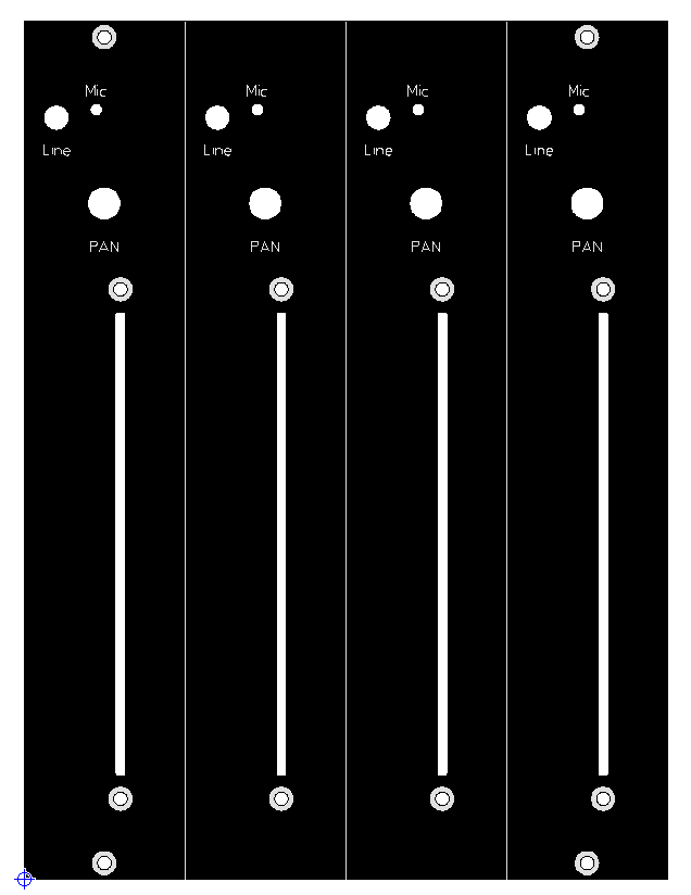
Here's what I've come up with.  I'll use the 508 front brackets from Jeff for mounting.  So that's fader at the bottom, pan, then mic/line toggle and mic indicator LED. 


Edited to add:


I guess we'll see if stuff fits. 
 
Krcwell said:
Center panned, I'm at -17dB, so approx. -5dB from hard panned.  Jeff's panning schematic says it will give approx. -4.25dB pan law at center.  Given the rather mediocre testing setup I'm using, I figure the -5dB I'm seeing is close enough.  It sounds very natural throughout the panning spectrum thus far. 

Unless my logic is totally off, everything seems to be working as it should.  However, I would appreciate if someone could confirm or deny that!

Thanks,

Keith
[/quote

Hi Keith,

your logic isn't completely off, everything seems ok with your tests. But it was a bit hard to understand. It seems that you are talking about dBFS most of the time even if you call it dB.

It would be clearer if you would use the good units.

dBFS : digital scale OdBFS = Full Scale
dBV: analog voltage level 0dBV = 1V
dBu: analog voltage level UdBu = 0,775V
dB: refers to a gain (or loss) in any scale.

As for the frontpanel, it seems to be just fine.

Cheers,

Thomas
 
totoxraymond said:
Hi Keith,

your logic isn't completely off, everything seems ok with your tests. But it was a bit hard to understand. It seems that you are talking about dBFS most of the time even if you call it dB.

It would be clearer if you would use the good units.

dBFS : digital scale OdBFS = Full Scale
dBV: analog voltage level 0dBV = 1V
dBu: analog voltage level UdBu = 0,775V
dB: refers to a gain (or loss) in any scale.

As for the frontpanel, it seems to be just fine.

Cheers,

Thomas

Thanks Thomas! Very good point about using correct units of measurement. I haven't really wrapped my head around dBV, dBu, etc... But then again I haven't put much effort in to understanding. I think I've found my learning topic for this week.

Based on your description, it does look like my unit of measurement was dBFS. I'll take a look at the metering plugin I was using and see if it provides any indication of the unit of measurement.

With dB itself measuring the gain or loss in any scale, is it correct to say that a decrease from 0 dBV to -5 dBV / 0 dBu to -5 dBu / 0 dBFS to -5 dBFS would all be a decrease of 5 dB?

Thanks again Thomas, I appreciate the knowledge!
 
Krcwell said:
With dB itself measuring the gain or loss in any scale, is it correct to say that a decrease from 0 dBV to -5 dBV / 0 dBu to -5 dBu / 0 dBFS to -5 dBFS would all be a decrease of 5 dB?

Yes, it's correct.

Usually, plug-ins give you reading in dBFS, unless you are using some very particular metering plug-ins which can convert into dBVU, dBppm... the waves Dorroughs plug-in is one of them.

The difference between scales is the domain (digital , analog electronic, acoustic...) and the 0 reference.

It's not very complicated  beside that.

Thomas

 
Back
Top