Starting a modular console - CAPI/GDIY 508 rack build

GroupDIY Audio Forum

Help Support GroupDIY Audio Forum:

This site may earn a commission from merchant affiliate links, including eBay, Amazon, and others.
I'm circling back to power supply. The main driver being I want a seperate 12v rail for relays, led's, vu's, etc... The test fader/pan panel should be here early next week, and hopefully all goes well with that. The last, unbuilt and untested piece of the pie is the mic/line relay switching using the CAPI plug in relay boards.

I currently have a CAPI/GDIY dual vpr power supply, which provides a total of 3 amps @ +/- 16v, or enough to power 22 500 series modules at (I think) max spec'd draw of 130ma per +/- rail. Now, a lot of the modules I have won't be drawing anywhere near 130ma, but when you add up 12-16 mic pre's, 12-16 eq's, at least 40 more 2520's for the fader and ACA's (I'm factoring 30ma/rail/2520), 3 amps is gonna fall short.

I figured 6 amp +/- 16 with 1.7 amp +12v and 0.5 amp +48v for phantom would do the trick. I was looking at about $320-$350 for the four International Power linear PSU's:

Krcwell said:
Looking at the International Power Open Frame line, I've compiled the following hypothetical power supply that should  fit into a 3u 14" deep rack case.

2 x 15V 6A    http://www.galco.com/buy/International-Power/IHD15-6.0
Wired as described in the thread linked earlier, these would provide +/-16v rails with 6A.  It appears that these PSU's can easily be adjusted to 16v, but I need to do some more research on that.

1 x 48V 0.5A  http://www.galco.com/buy/International-Power/IHB48-0.5
For phantom power.  Should be more than I ever need.

1 x 12v 1.7A    http://www.galco.com/buy/International-Power/IHB12-1.7
For relays, LED's, meter lights, etc...

but Gary made a good point:

gar381 said:
Prebuilt manufactured supplies are a great way to go and
Can be a  great cost savings over higher amperage  DIY supplies .

SPHERE_PSU272.jpg


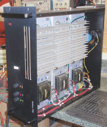
I ebayed these 3  13 Amp  "Power One" used supplies at $38 each.
for my Sphere Sidecar and they work great.

Shop around Keith :)

GARY

I did shop around, and through random ebay and amazon finds, I have the exact PSU's I listed before used for just over $100 total. Sage advice: shop around. Outside of needing to clean up some clipped off wires from a couple terminals, they all look perfectly fine (note: haven't tested them yet).

Next step will be to figure out how to wire them all together in one enclosure. I'll probably start a seperate thread about that, but will link it here.

All for now,

Keith
 
Test fader and pan faceplate is in from FPE. 


I decided to just do the engraving on one channel, to test out spacing, layout, etc...  I still need to figure out the fader scale specific to the CAPI 2S-LA and Alps K faders, so this panel will probably end up being a $70 burner, but I think that's worthwhile for a test faceplate.  I'm already in too deep, no need to start cheaping out now.

And testing the fit of the faders, pan/sum pcb's, and mic/line switches:


The mounting holes for the faders seemed slightly a touch far apart, but once fully screwed in they fit snug.  Not sure if this is normal with fader mounting or if I need to move the mounting holes a hair closer.

A closeup of the mic/line and pan engraving with a 1/2" aluminum pointer (sigh...)


Dammit, those knobs look so good, and I only have 2... I'm not even going to get started.  Just saying I'm glad I sold my 3124 a while ago and spent it all at the CAPI store. 

So, if not obvious, those knobs are no longer available (still need to try ordering direct...), which is disheartening.  I had some 15mm Sifam pointers on hand, so tried those out instead:


Now granted, things would look much better if I had some 15mm knob caps on hand, but I don't. 


I think I can grow to be ok with it once I get some caps and nut covers for these knobs, but still holding out some hope I can get my hands on enough of the aluminum pointers.

I also wanted to point out the spacing between the fader maxed out and the pan knob:


I didn't consider the spacing of the cutouts in FPD too much, just kinda threw together what looked right.  I might end up extending the panel a little bit, or maybe moving the fader mounting holes down some, to increase space between max fader and pan.  I don't really plan to max out the faders all that much, but still something I'm pondering.

That's all for now.  I'm figuring out a measuring system for determining the fader scale markings from +12 to -infinity.  More to come on that soon.

 
Keith

The way I did my Sphere project Faders was easy.

Pull Fader down until you got +4dbu AFTER the fader amp.
Measure the distance from the Bottom Fader Mounting
Screw to the middle of the Fader Knob with a Machine rule.

Set your  origin in FPE to the bottom Fader Mounting Hole
and transfer  the measured distance to FPE.  This is your "0"
Fader line.

Pull fader down until you get -1dbu after the fader amp.
Measure the distance again and transfer to FPE.  This is
your -5db line.

Repete this process for all other markings and you will be golden.

hope this Helps.. :)

GARY
 

Attachments

  • FADER.gif
    FADER.gif
    8.9 KB · Views: 72
Thanks Gary. I appreciate the signal diagram! And does it look like I'm not the only one who uses MS paint?

You describe pretty much the concept I have in mind. I was thinking that lining up a ruler at the bottom edge of the faceplate would provide a more consistent zero vs. trying to align with the center of the bottom fader screw hole. I don't have a well made or precise ruler, so I am going to print some 1 foot 1/32" rulers, verifying the printout with a tape measure, and just slap one down on the panel with the zero aligned to the bottom. Mark the various db points I want on that using the method in your signal diagram, then place them with FPD using the bottom of the panel as height reference. Im using 20% tolerance faders, so I'm assuming nothing will ever be perfect. I figure my half-assed method will get me close enough.  This is on my to-do list for tomorrow, so I'll post some pics.
 
For the fader metalwork, did you use Jeff's vertical 2-508 bundle? Or did you design metalwork just for the faders?
 
magnified said:
For the fader metalwork, did you use Jeff's vertical 2-508 bundle? Or did you design metalwork just for the faders?

I'm using the 2-508 frame for testing purposes, but that metalwork is too deep (a little over 6 inches deep, I'm looking for a depth of ~3-4 inches) for my planned final layout, and the fader/pan panel won't be the height of 2 500 series modules. Right now the panel is 8" tall, I might end up at 8.5-9" tall, still playing around with it. I plan to use the front mounting brackets from Jeff's 508 design, but will get some raw aluminum top/bottom and side frame pieces made in my next FPE express order.
 
Krcwell said:
Dammit, those knobs look so good, and I only have 2... I'm not even going to get started.  Just saying I'm glad I sold my 3124 a while ago and spent it all at the CAPI store. 

So, if not obvious, those knobs are no longer available (still need to try ordering direct...), which is disheartening. 

Hello Krcwell,
first of all I want to say that you are doing a great project here, everything looks good and well planned, congratulations and can´t wait to see the Finished beast.

As for the Knobs I completely understand, I also have the same problem, need to finish a project that already did the faceplate for those knobs and cant get hold of them anymore.
Would like to say you are thinking in buying direct and need more orders, I would join you and I'm sure some more people in the Group would join also.
They probably only sell big quantities.

Thanks
 
I'm actually starting to think that Jeff's temp knobs might look kinda classy on this:

CSK-150-back.jpg


Edit: I'm really starting to like these. I'm gonna order a few up, see how they look in place.
 
Random post...

Aside from desiring to be an audio nerd (I would consider that a compliment) I was born and raised a computer nerd. I've been toying with setting up an arduino to control a panel of these mini OLED screens that are ~1 inch wide for channel labeling.

w8.jpg


(Note: I did not take this picture, I took it from Google images)

They're excess 128x64 cell phone screens, where the top ~1/4 is yellow, the rest blue. Group assignment would appear in the yellow section, track name in the blue. Toss an ~2 inch tall panel with one of these little screens for each channel between the fader panel and the pre/eq buckets, should be able to run it all via usb from the DAW computer... That could be cool. I have 4 screens that should be delivered tomorrow to play around with.
 
Very cool Idea!!

I actually toyed with the Idea of Building a side car very close to yours based on DIY 1084 and API 312/550b cards. I had an idea of using the Arduino to control destructive solo mute logic. Still something I would love to try and do some day.  Great project by the way!
 
It's been a while.  I got a promotion at work mid-October, then it seemed that for the remainder of the year I did nothing but work... funny how that happens.

I've also been working on a little side project, trying to put a Harrison Ford Filters pcb and an API 553 eq in a 500 series.  I figure the combo would make a great tracking EQ that's also pretty useful for mixdown.  There's another thread for that: http://groupdiy.com/index.php?topic=60363.0

But back to the console.  First off, the knob situation.  I decided to order 4 of Jeff's hold me over knobs mentioned earlier, and I like 'em.  Quality and classy.  This picture really doesn't do them justice:


As far as the fader front panel, I've decided that I'm going to turn this in to two panels; one will be fader and mic/line switch, the other will be for the pan.  It makes the most sense for future proofing.  Now that Jeff has all those dual concentric BI pots for sale, I haven't been able to stop my mind racing about adding some cue and aux sends, maybe another couple busses... so the Pan panel will eventually change, but the fader and mic/line switch panel will not.  A bit more expensive up front, but will save money in the long run whenever I get around to upgrading.

But, that is in the future, and my main goal is getting the basic single bus done.

I put together a pair of PCB's to take care of the mic/line switching that will feed the eq bucket.  The first being a pcb to handle the connections to the CAPI Plug in Relay boards:


Mic in will be from the mic pre bucket, line in will most likely feed directly from the DAW interface line out, and to EQ will feed the EQ bucket.  Then from there EQ feeds normalled patchbay, patchbay out multed to feed DAW interface line in and 2S-LA input.  Side question: is it cool to mult from a patchbay like this?

And the other being to hold the switches and led's for the fader front panel:


I ordered a batch of prototype boards for each from pcbcart.com, those are due in Tuesday.

Next on the list is getting the power supply sorted.  I ordered a basic 3U case from collective cases (that should hopefully be arriving soon) that I plan to use to house the International Power linear PSU's.  I got some really helpful feedback on the other thread that I linked to a few posts ago, and think for the most part I've got it figured out.  I'll probably need to play around with the grounding a little bit, some of that is still confusing, but as far as stuff that can kill me, I'm mostly confident.  Here's hoping that statement doesn't come back to bite me in the a$$.

Other next steps:

1) Redesign front panel to move pan to it's own panel. 
2) Figure out some sort of chassis for the fader and pan front panels.

That's about it for now.  Winter has finally fallen upon the midwestern US, so there's no better time to get some progress done on this build.  Hopefully updates will be far more frequent than they have been.

Thanks,

Keith
 
I'm hoping your power supply doesn't hum mechanically. Every power one/acopian ebay special that I've bought hums enough to need a machine room if you're doing quiet tracking in the control room. I built up a big overkill +/-24V supply for my board and it annoyed me enough to go back to the original power supply. Just something to look out for.

Great job so far though!
 
I have three Acopian AO50PX24F in my rack and they are dead quiet and have been reliable for many years. Adjustable 24 volt, 2.5 amp.  They are 2U, white face with two meters, one for voltage and one for amperage.  I got these off ebay for less than  $100 each. I highly recommend these if you can find them.  2 units wired up as a pair for bipolar of coarse.
 
gar381 said:
My 3 power one 24v supplies are dead quiet as well.

BTW Krcwell.. all is looking GREAT so far.  Isn't scratch building
consoles FUN !! ;) :) :)

GARY

Just realized I started this thread over a year ago... Nowhere near as easy as I originally thought, but a great learning experience!  Hopefully I'll have something to show for it before this thread hits year 2...
 
Time for another update...

Metalwork is a pain in the a$$.  This has been the biggest holdup in progress as machining, designing, etc... metal work is far outside my skillset.  Turns out making something "custom" is nowhere near as easy as buying pre-fabbed metal for the various projects I had completed prior to this. 

Front Panel Express makes the process rather easy, but the catch was that I'm trying to make an aluminum chassis for the fader panels to mirror up with the beautiful 508 racks I got from CAPI.  The 508 racks use 1/8th inch aluminum.  Front Panel Express, for all that they offer, seem stuck on the makes-more-sense-but-I-think-it's-stupid-because-I'm-American metric system, only offering 2, 2.5, 3 and 4mm thicknesses as standard.  I explored sourcing 1/8th inch aluminum with the same ease and flexibility of design (along with decent pricing) as Front Panel Express, but that was one dead end after another.

So, I figured I would make the 3mm work.  The standard size for the cross pieces of the 508 rack are 12.003", so I rounded up to 12.010" assuming that the side support pieces would be 3mm, thus losing ~0.007" vs the 1/8th inch aluminum.  I know the math isn't perfect, but allowing for a little slop in tolerances, I hope this ends up working out.

I got one of the test fader chassis horizontal pieces back from FPE about a week ago, and thankfully I've got the drilling pattern right to align with the same front brackets used on the 508 rack.  A couple of pics:


I got some 1.5" corner braces from McMaster Carr, I think they will end up working out.

I also finally did some measurements on my test fader panel to determine correct db markings, here's what I've come up with:


I've compared to pics of other API consoles, and it seems to be pretty close, except for the larger than expected distance between -12 and -24.  I triple checked measurements on multiple faders, and I keep coming up with the same spacing, so the hell with it; good to go.  I'm going to order up a test faceplate with this engraving, double check everything once again, then finalize the measurements for the vertical sides of the fader chassis.  I'm just happy that I'm close to overcoming this "custom designed metalwork" obstacle that has been both a mental and physical impediment to progress on this project.

On a side note, my little 553/Harrison Ford Filters eq that I plan to use for a good amount of the channel eq's is coming along nicely:


More to come.  Thanks for reading.

Keith

 
For the metal work also consider finding a local shop to do the work. Some are open to small quantities and face to face communication can be a huge plus.
 

Latest posts

Back
Top