Studer 169 EQ in API 500 format

GroupDIY Audio Forum

Help Support GroupDIY Audio Forum:

This site may earn a commission from merchant affiliate links, including eBay, Amazon, and others.
irfrench said:
...

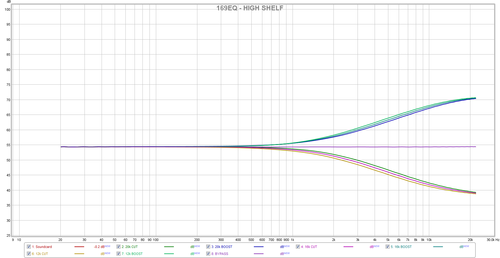
This includes the switch-able additional LF and HF shelf frequencies with lowest/middle/highest freq. select for the mid-band section.

Enjoy?  ;D

At least it explains why I heard the HF shelf differences as being quite subtle!  ;)

Ian,
8)

That's not only great work Ian, but also great timing as I haven't gotten around to modding my units yet... :)

Extrapolating somewhat from your lowest setting on the LF shelf (28hz), I suspect that stock (20hz) is actually pretty much perfect for my needs as only judging by my eyes, it looks like even the 28 hz setting is a bit too strong a bit too high up in the low frequency range (though obviously that's just my own preference and probably a result of having done most of my eq'ing in daws where it's a more precise instrument).

Going by your graphs (and assuming I'm interpreting them correctly), I probably won't choose to mod the freqs on my units, but if I were to play with it, I think I'd be tempted to go lower rather than higher... (15, 20, 25 perhaps...or whatever the alternate values (330 & 470 nF) work out at!)

Kaz
 
I just finished two of these little beauties! Original Studer transformers with 5534's for now.

Tasty! Though one doesn't work due to a busted primary winding on the transformer.
Only limited use so far but on snare that sound great!


Here is a front panel file since know one else seemed particularly keen to share theirs. It has rear cutouts to hide potentiometer nuts.

https://www.dropbox.com/s/zqapmn7neidrcrf/169K5%20The%20Lab.fpd

 
irfrench said:
At least it explains why I heard the HF shelf differences as being quite subtle!  ;)
tumblr_inline_mups2cmUut1r2bfgn.png


[quote author=irfrench in his blog]

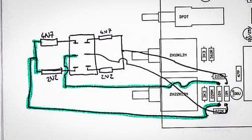
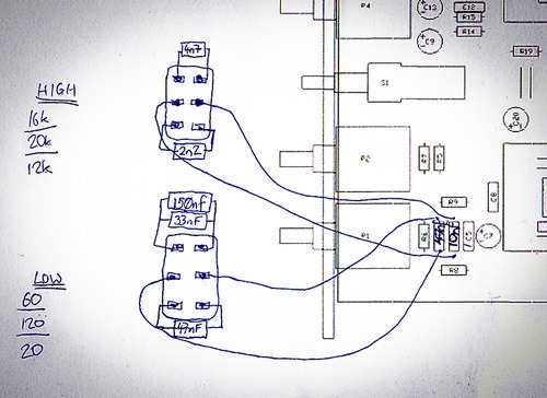
This is how the modded caps need to be added in. No probs.

tumblr_inline_mtn3tvTovd1r2bfgn.jpg

[/quote]


Yes probs. That doesn't work. For the high filter you need to switch C4 and C5. A double pole switch for the high filter and a single pole for the low filter will do the job (one side of each capacitor is permantly connected). Also note in your frequency calculations that the capacitor(s) on the PCB are in parallel with the capacitor selected by the switch: Ctotal = Cpcb + Cswitch.


Audiox,

Thanks for pointing this out - it explains why I didn't get the results I expected.  I'll update the blog and make sure no-one else uses this.

So to make the HI switchable I can modify the switch as it is already (because C4 and C5 on the PCB are both already 10n) and replicate the 4n7 and 2n2 using both halves of the switch?:

tumblr_inline_mvdrdbZsWC1r2bfgn.jpg


Thanks again for pointing this out.

Ian
:)

 
Me again  :eek:

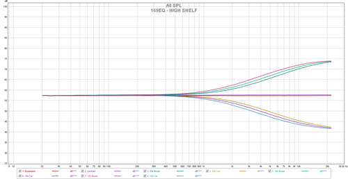
Just a quick note to say I made the changes (above?) and the EQ curves became:
tumblr_inline_mvei2pvGQa1r2bfgn.png


A bit more separation and the differences now are definitely less subtle!  ;)

I also wanted to do a comparison (for my own curiosity) between the IC and DOA options - so I ran a short recorded acoustic passage out to the same EQ, once with IC's once with DOA's.  I hope it is of interest:

https://soundcloud.com/minoian/sets/oa10-comparison  https://soundcloud.com/minoian/sets/169eq-doa-comparison

Thanks,

Ian
:)


EDIT:  LINK UPDATED SEE REASONS BELOW
 
irfrench said:
Me again  :eek:

Just a quick note to say I made the changes (above?) and the EQ curves became:

tumblr_inline_mvei2pvGQa1r2bfgn.png


A bit more separation and the differences now are definitely less subtle!  ;)

I also wanted to do a comparison (for my own curiosity) between the IC and DOA options - so I ran a short recorded acoustic passage out to the same EQ, once with IC's once with DOA's.  I hope it is of interest:

https://soundcloud.com/minoian/sets/oa10-comparison

Thanks,

Ian
:)

The OA10 sounds like it has something wrong (or it's just way noisier....)
 
Yeah the noise difference is definitely noticeable - I'd not heard any direct comparisons made like this hence why I thought it may be useful to compare them.

I'll try swapping the OA10s around a bit tomorrow and see if anything changes with each DOA.

Has anyone else got similar comparisons they can share?

Ian
 
The noise sounds more like coming from a dynamics tool because it is fading in/"coming back" during the long sustain phases only,doesn't seem to be a static noise floor.Maybe the original recording has been treated during or after capturing.

Best,

Udo.
 
Hi.

Listening back I hadn't realised the noise was that prominent - I really need to be double checking everything and not rushing things... Helpfully I hadn't saved those source wavs so had to redo with a different section.  Did the same thing as last time (I'll remove the previous link) making sure no compression was on anything-anywhere, as kante says I think there was some loudness maximisation going on.

https://soundcloud.com/minoian/sets/169eq-doa-comparison

Ian.
 
Hi Ian,

thanks for posting the new samples!
From what I hear (using headphones atm) the difference is very small,it seems the NE5534 sounds a little bit more "boomy" at the low note at sec.7 to 8,but it could be a body/room resonance as well.
Both versions sound really nice and aren't off from each other too much.
I would like to know how these will sound when running a bit more complex material through it.
For me just another indicator that using an "old" NE5534 in a good design is still an excellent choice,isn't it?

Best regards and have fun,

Udo ;)
 
You're absolutely right, the NE5534s sound pretty darn good! 

I do however *think* or *feel* I prefer the OA10s more though - I did a few blind AB'ing tests and ended up picking the OA10s all the time, they seem to add a bit of bite(?)/complexity to it.

If anyone is thinking about building these - do it!  They really are great EQs.

Thanks again to Audiox/Gustav for making these so accessible.


Ian
 
Ok looking for some help as I must have done something stupid. Seems like an easy build so I build two. One with transformer and 2520's and one without transformer and 5534p. Both are doing the same thing. My 500API rack won't power up when they are plugged in. Any thoughts?

Thanks in advance

Daniel


Attachments

  • photo 1.JPG
    photo 1.JPG
    175 KB
Do you have a way to test it outise the rack? like a card extender?
Is there any smoke? do all modules run fine without the 169 inside?

Check continuity from + to 0v and - to 0v.

Just my opinion!
 
Hi

I´m thinking in adding a HPF on this EQ, would it work inserting it before C3 (after the first IC)?

This is the Filter schematic:
20Hz-to-200Hz-variable-high-pass-filter-1326382791.gif


My only reason to use this is because it´s the easier I´ve found right now, I don´t need nothing fancy, just filter some low freqs. Also, I think the TL072 will drive finely the eq or I´m wrong?

Any ideas/suggestions?
 
dirtyhanfri said:
I´m thinking in adding a HPF on this EQ, would it work inserting it before C3 (after the first IC)?
ignoring level mismatch by missing/not shown bypassing of the HPF, probably yes.
My only reason to use this is because it´s the easier I´ve found right now, I don´t need nothing fancy, just filter some low freqs. Also, I think the TL072 will drive finely the eq or I´m wrong?
Drop the gain of the balanced line receiver by 3dB to compensate for the HPF filter boost (maybe solder 23K71 resistors in parallel to the 10Ks R3 and R4 for ideal close matched value 7K071s). Sourcing dual rev.log 47K pots might be the hardest part. A dual pole switch for one or more HPF freq. might be easier to source. Don't leave the other half of the TL072 unconnected. Maybe have a look at the Barry Porter NetEQ HPF section for a similar/bypassable approach.
 
Thanks for the answer Harpo

Well, maybe i didn't explain my plan ok.

The idea is using a Lorlin 2 way 6 positions switch for the freq selection.

To bypass it I was thinking in a simple dpdt.

For the other half of the TL072, what do you suggest? route to ground the three pins?

And the level mistmatching you mention, would be gone with the hpf bypassed? (Sorry, but I'm still learning a lot of concepts) So, there's a boost in the schematic attached? Maybe messing with the value of the resistor between pins 1 & 2 of the IC will solve it?

I'm modding the audiox pcb design to include it, I could share it if there's interest, it's quite ugly right now, as I don't need the API 500 format I reduced it a bit, I think I can make a stereo version in a eurocard.

 
dirtyhanfri said:
The idea is using a Lorlin 2 way 6 positions switch for the freq selection.
To bypass it I was thinking in a simple dpdt.
As suggested and not shown on your pic. If you make the full CCW setting of your switched HPF low enough, this might operate like a bypass.

For the other half of the TL072, what do you suggest? route to ground the three pins?
Place a -3dB voltage divider in front and use the TL072 2nd.half to buffer this attenuator if you want to implement a bypass switch. With HPF always in circuit, dropping the gain of the balanced line receiver as previously described seems the easier solution. (as previously mentioned, have a look at the NetEQ).

And the level mistmatching you mention, would be gone with the hpf bypassed? (Sorry, but I'm still learning a lot of concepts) So, there's a boost in the schematic attached? Maybe messing with the value of the resistor between pins 1 & 2 of the IC will solve it?
Your pic shows an equal value sallen-key filter. This type has gain in the pass band. Sallen-key filters with unity gain in the pass band will not have equal values for the frequency setting C and R parts values.
 
Back
Top