ruffrecords
Well-known member
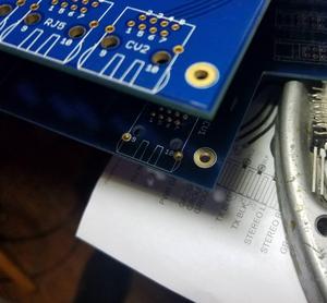
I have just been testing a new version of my four toggles PCB that does phantom, pad, mic/line and phase switching. It is the same schematic just with the switches arranged in a square instead of in a single column. To aid wiring up to it I had marked the hot pin on the 3 pin Molex connectors I use to connect mic, line and the output. Wired it up and odd things happened. Mic/line switch did nothing - mic signal still came through. 20dB pad did nothing but phase switch reduced level by about 6dB. Realised I had left some component soff the PCB. Fitted and retested - very similar results. I began to suspect I had made a mistake in the PCB layout so go back to computer and load up PCB layout onto screen. Carefully check all traces - nothing wrong. Peer at PCB layout for about half an hour and then it hits me. I had rotated connectors at some point to ease tracking but I had not moved the silk screen letter H used to indicate which pin was hot. The H was next to the screen pin!! Rewired the test PCB ignoring the 'H' and it all works perfectly.
Cheers
Ian
Cheers
Ian

")