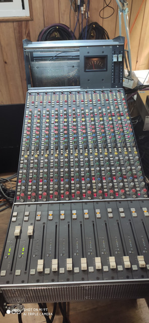
Summing fader module Studer 980 mixer in Calrec S2 sidecar.

GroupDIY Audio Forum

Help Support GroupDIY Audio Forum:

This site may earn a commission from merchant affiliate links, including eBay, Amazon, and others.

AudioIngenia

Well-known member
Joined
Feb 22, 2017
Messages
68
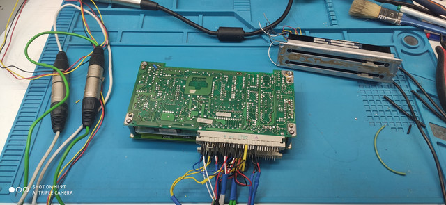
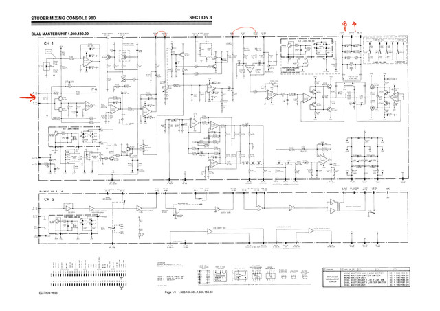
I'm testing the summing fader module of a Studer 980 mixer in a Calrec S2 sidecar.
I get the sound on the output,  it seems that the sound is correct.
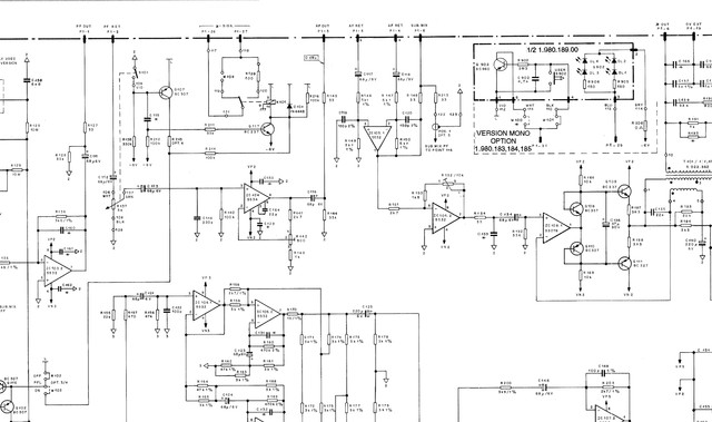
See attached image. I don't like the bridge on the postfader insert.
It is an unbalanced output to balanced input. How can I modify that? Any suggestion?
 
AudioIngenia said:
I'm testing the summing fader module of a Studer 980 mixer in a Calrec S2 sidecar.
I get the sound on the output,  it seems that the sound is correct.
See attached image. I don't like the bridge on the postfader insert.
It is an unbalanced output to balanced input. How can I modify that? Any suggestion?

Why do you think you need to?  The signal path inside the mixer is unbalanced. Feeding unbalanced into a differential will maintain signal integrity.

JR
 
I've already tried that.
I have connected from pin 3 to pin 8. The signal does not flow. While from pin 3 to pin 4 or 5 if the signal passes... :(
 
AudioIngenia said:
I've already tried that.
I have connected from pin 3 to pin 8. The signal does not flow. While from pin 3 to pin 4 or 5 if the signal passes... :(

I can't read the pin numbers on that drawing but I will ASSume one is the differential + input, and the other is the differential - input. If you connect the + output to the - input you will realize a polarity inversion.

Ideally the differential - input should be connected to the audio 0V output to forward reference between the two local audio grounds.

Ian's suggestion to impedance balance, means adding a similar resistance in series with the low send to preserve common mode rejection ratio. This might make more sense if the signal was being sent across a significant distance in a noisy environment, "and" the input was actually balanced, but from observation it looks like a simple differential (still good).

JR
 
Hello

Just as a note, as it's useless if you don't want the AF insert, but you have two bal to unbal and two unbal to bal blocks in this unit, autonomous... free to wire as requested by the user/operator.
I suppose you have them as options in the patch, or hard wire at the back plate pcb for permanent bal insert

Best
Zam
 
Yes, my intention is to use the prefader insert with the balance & unbalance stages.
Where I'm stuck is like bypassing the postfader insert

 
AudioIngenia said:
I've already tried that.
I have connected from pin 3 to pin 8. The signal does not flow. While from pin 3 to pin 4 or 5 if the signal passes... :(

Pin 8 is a sub-mix in. You should not use that pin. To bypass the insert you need to connect pin3 to pin5 and separately connect pin 4 to ground.

Cheers

Ian
 
Fantastic. Here he is singing. Connected the pin 3 to pin 5 and pin 4 to ground.
I used the balanced / unbalanced stages in the prefader insert.
One last question. The Calrec sidecar works at 16v and the Studer circuit works at 15v
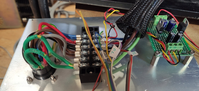
Should I reduce the voltage? I have a 7815 and 7915 ready for it.
 
AudioIngenia said:
Fantastic. Here he is singing. Connected the pin 3 to pin 5 and pin 4 to ground.
I used the balanced / unbalanced stages in the prefader insert.
One last question. The Calrec sidecar works at 16v and the Studer circuit works at 15v
Should I reduce the voltage? I have a 7815 and 7915 ready for it.
The 7815 and 7915 are not suitable for dropping 16V rails down to 15V you would need to use LDO (low drop out) regulators.

JR
 
AudioIngenia said:
Fantastic. Here he is singing. Connected the pin 3 to pin 5 and pin 4 to ground.
I used the balanced / unbalanced stages in the prefader insert.
One last question. The Calrec sidecar works at 16v and the Studer circuit works at 15v
Should I reduce the voltage? I have a 7815 and 7915 ready for it.

As JR said, the 7815 and 7915 need a higher input to work properly, the cheap solution is to add a couple of diodes in series, the output voltage will be around 14.6V, not too bad...
 
Hello

The 980 modules will probably work fine at +/- 16V ?
-maybe check Vref (IC100) voltage at input
-reserv caps at +/- 15 input are ratted for 16v at schemo, if it's the same at pcb replace for 25v

Best
Zam
 
zamproject said:
Hello

The 980 modules will probably work fine at +/- 16V ?
-maybe check Vref (IC100) voltage at input
-reserv caps at +/- 15 input are ratted for 16v at schemo, if it's the same at pcb replace for 25v

Best
Zam

Probably but I am reluctant to give such advice. Adding two diodes in series (something like 1n4001) is cheap and easy.

JR
 
I have definitely built a 7815 and 7915. The voltage is above 17v. Now the whole set works great.
Thanks for your help
I open a new topic for an anomaly that has arisen

 
I have definitely built a 7815 and 7915. The voltage is above 17v. Now the whole set works great.
Thanks for your help
I open a new topic for an anomaly that has arisen

I have definitely built a 7815 and 7915. The voltage is above 17v. Now the whole set works great.
Thanks for your help
I open a new topic for an anomaly that has arisen

Sorry to hijack an old thread, I am currently in the process of putting together an S2 sidecar, I am using the same 12 mono PQ4068 modules - trying to locate a pinout for the EDAC 56 pin Line i/ps & o/ps and the 38 pin Mic i/ps. I have tried standard TRS combinations with limited success. Any help would be much appreciated. Thanks in advance!
 
While some people who sing have a mirror in their bathroom, I have a couple of S2 sidecars.
All the 56 pin EDACs have 12 pairs of balanced audios. and run AB chan 1 left. CD chan 1 Right. EF Chan 2 Left JK chan 2 right, The only ground (screen) pins are the 4 on the centreline.
The 38 for mic ins are EF chan 1 left JK Chan 1 Right.
All pins except the 4 stereo inputs are chassis ground.
Putting diodes as 'droppers' is the easiest solution as there is not sufficient voltage headroom for LM series regulators and the pos and neg variants (78/79) have different dropout voltages anyway.
Matt S
 

Latest posts

Back
Top