T.bone SC 450 mod to sound like U87

GroupDIY Audio Forum

Help Support GroupDIY Audio Forum:

This site may earn a commission from merchant affiliate links, including eBay, Amazon, and others.

Arbolito

Member
Joined
Dec 24, 2023
Messages
19
Location
Netherlands
Hello everyone!

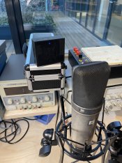
After countless reading in and out of these forums, here's my simple capsule replacement mod. T.bone SC450 (80€) with a replacement K67 capsule. As the t.bone microphone circuit is the same as MXL2001/V67 (whose first stage is same as u87), which already provides HF attenuation, it should sound quite close to the Neumann.

I scraped some paint from the t.bone microphone for a vintage look, and did a not very scientific comparison against a real Neumann u87 (very old one). The capsule inside purple circle is the new one, the other is the old one. I had to drill some holes in the microphone to fit the new one.

The audio files are Z and Y: does one sound better to you than the other on this source?
Y:View attachment micY.wav

View attachment micZ.wav
Z:
 

Attachments

  • IMG_2732.jpg
    IMG_2732.jpg
    1.8 MB · Views: 1
  • IMG_2733.jpg
    IMG_2733.jpg
    1.4 MB · Views: 0
  • IMG_2729.jpg
    IMG_2729.jpg
    1.7 MB · Views: 1
Last edited:
As the t.bone microphone circuit is the same as Neumann U87
The circuits are not the same AFAIK.
I scraped some paint from the t.bone microphone for a vintage look
I like that, I think it's the first "reliced" microphone I've seen here. The old U87 looks beautiful (y)
and did a not very scientific comparison against a real Neumann u87 (very old one).
The sound is different but the source is not the best for comparison. The second sample got more low end, I think its the Neumann.:cool:
 
Last edited:
Hi Arbolito,
What self-noise does sc-450 stock have? (compared to Neumann or other reliable microphone)
The specifications published by the manufacturer are not real.
From the diagram I would say it is about 18..20dBA
Try doing some vocal tests, with pink noise, etc.
 

Attachments

  • Screenshot_2024-01-19-15-30-40-481_com.google.android.apps.docs.jpg
    Screenshot_2024-01-19-15-30-40-481_com.google.android.apps.docs.jpg
    936.3 KB · Views: 1
Hi Arbolito,
What self-noise does sc-450 stock have? (compared to Neumann or other reliable microphone)
The specifications published by the manufacturer are not real.
From the diagram I would say it is about 18..20dBA
Try doing some vocal tests, with pink noise, etc.
Not sure about the stock one.

Today I changed C1 10nf to 33nf, and C3 220pf to 540pf.

After modifying it, I compared it on an old celesta with a tlm102, and mine is noisier, in the end of these audio files you can notice noise on mine, and the tlm102 has barely any.
 

Attachments

  • sc450.wav
    1.7 MB
  • tlm102.wav
    1.7 MB
Not sure about the stock one.

Today I changed C1 10nf to 33nf, and C3 220pf to 540pf.

After modifying it, I compared it on an old celesta with a tlm102, and mine is noisier, in the end of these audio files you can notice noise on mine, and the tlm102 has barely any.
Arbolito,
can't open .wav attachments
 

Attachments

  • Screenshot_2024-01-19-18-52-44-680_com.android.chrome.jpg
    Screenshot_2024-01-19-18-52-44-680_com.android.chrome.jpg
    294.5 KB · Views: 0
Arbolito,
The sc-450 is much noisier than the TLM102!
The input circuits have a different implementation of the first jFET transistor.
And t.bone only has 31V capsule bias,(half compared to Neumann), the capsule sends less signal to the jFET transistor, so the signal to noise ratio is much worse. You need to increase the polarisation voltage of the capsule, (about 60v) by adding a simple converter
dc/dc and dropping resistor R18 from 4.7k to 3.9k to keep the 2SK170 and 2SA1015 transistors voltages for initial bias. Some resistors are removed:
R15, R16, also the capacitors C13, C14, and the output voltage(60v) from the dc/dc converter is injected into the free end of the resistor R17 330k, decoupled with a filter capacitor with a voltage of 100V. It does not need a large value, the polarization current is very small (it can be 47nF...220nF).
It will increase the output level of the microphone by a few dB, improve the S/N ratio and at higher SPL you will have a nice magnetic saturation of the output transformer.
I attached the schematic of a DC/DC converter.
 

Attachments

  • Screenshot_2022-05-31-09-03-19-552_com.google.android.apps.docs_1705682695372.jpg
    Screenshot_2022-05-31-09-03-19-552_com.google.android.apps.docs_1705682695372.jpg
    328.8 KB · Views: 4
Last edited:
Arbolito,
The sc-450 is much noisier than the TLM102!
The input circuits have a different implementation of the first jFET transistor.
And t.bone only has 31V capsule bias,(half compared to Neumann), the capsule sends less signal to the jFET transistor, so the signal to noise ratio is much worse. You need to increase the polarisation voltage of the capsule, (about 60v) by adding a simple converter
dc/dc and dropping resistor R18 from 4.7k to 3.9k to keep the 2SK170 and 2SA1015 transistors voltages for initial bias. Some resistors are removed:
R15, R16, also the capacitors C13, C14, and the output voltage(60v) from the dc/dc converter is injected into the free end of the resistor R17 330k, decoupled with a filter capacitor with a voltage of 100V. It does not need a large value, the polarization current is very small (it can be 47nF...220nF).
It will increase the output level of the microphone by a few dB, improve the S/N ratio and at higher SPL you will have a nice magnetic saturation of the output transformer.
I attached the schematic of a DC/DC converter.
Thank you for the advice to get a lower self-noise from the microphone. I think at this stage it would be below my skill level to effectively implement the dc/dc converter schematic into the circuit, there's not much free space in the microphone (if at all), and in the noise comparison I did with the TLM the microphones were 1.5m away from the source, and the source wasn't very loud, I was banging the old broken celesta to get anything out of it.

Hopefully the .wav files are correctly attached now for the TLM 102 noise comparison, and I've added 5 comparison files between 4 versions of my microphone, and the U87.

A) C1=10nf, C3=220pf
B) C1=6n8, C3=220pf
C) C1=47nf, C3=220pf
D) C1=33nf, C3=560pf
E) Neumann U87


450:View attachment scm450c.wav
Tlm:View attachment tlm102c.wav

A:View attachment A.wav
B:View attachment B.wav
C:View attachment C.wav
D:View attachment D.wav
E:View attachment E.wav


I'm very happy with the tone I get from my microphone (D) at the moment, its very close to the u87 (E) that I was going after, if there's any very simple to make it less noisy while keeping the same tone I would be very happy of course, but with close miking, or far miking on a loud source the noise won't give headaches.
 
Last edited:
Thank you for the advice to get a lower self-noise from the microphone. I think at this stage it would be below my skill level to effectively implement the dc/dc converter schematic into the circuit, there's not much free space in the microphone (if at all), and in the noise comparison I did with the TLM the microphones were 1.5m away from the source, and the source wasn't very loud, I was banging the old broken celesta to get anything out of it.

Hopefully the .wav files are correctly attached now for the TLM 102 noise comparison, and I've added 5 comparison files between 4 versions of my microphone, and the U87.

A) C1=10nf, C3=220pf
B) C1=6n8, C3=220pf
C) C1=47nf, C3=220pf
D) C1=33nf, C3=560pf
View attachment 120887
View attachment 120888
View attachment 120882
View attachment 120883
View attachment 120884
View attachment 120885
View attachment 120886


I'm very happy with the tone I get from my microphone (D) at the moment, its very close to the u87 (E) that I was going after, if there's any very simple to make it less noisy while keeping the same tone I would be very happy of course
Arbolito,
there is enough space in the microphone to add a small simple oscillator.
A few years ago I repaired an ADK 51s, I think it was called, with a scheme similar to the sc-450 and several dozen other Chinese microphones.
In addition to changing the de-emphasis network, changing capacitors, resistors, etc., I also increased the polarization voltage of the capsule. I built a small dc/dc converter point to point, exactly in the area of the removed resistors and capacitors.
It became another much better microphone.
That's what I mean by DIY.
There are no fixed rules, the greatest pleasure lies in experimentation and obtaining superior results.👍
 

Attachments

  • Screenshot_2024-01-19-19-50-04-439_com.android.chrome.jpg
    Screenshot_2024-01-19-19-50-04-439_com.android.chrome.jpg
    536.2 KB · Views: 2
  • IMG_20240119_194201.jpg
    IMG_20240119_194201.jpg
    4.3 MB · Views: 2
  • IMG_20240119_194529.jpg
    IMG_20240119_194529.jpg
    4.4 MB · Views: 3
Arbolito,
there is enough space in the microphone to add a small simple oscillator.
A few years ago I repaired an ADK 51s, I think it was called, with a scheme similar to the sc-450 and several dozen other Chinese microphones.
In addition to changing the de-emphasis network, changing capacitors, resistors, etc., I also increased the polarization voltage of the capsule. I built a small dc/dc converter point to point, exactly in the area of the removed resistors and capacitors.
It became another much better microphone.
That's what I mean by DIY.
There are no fixed rules, the greatest pleasure lies in experimentation and obtaining superior results.👍
Hi micolas, I see by your picture its not impossible after all, congratulations on the success. Say I attempt to follow your previous comment then, I would need to remove R15,16, C13,14, and then if I follow your dc/dc converter schematic, I would need to fit:

6 capacitors, 3 resistors, 2 inductors, 2 diodes, 1 transistor. And then my question is, where would I connect J1, as well as HDR1X2? Also, is the 500ohm_LIN a trim pot? Finally, the 5-15vdc battery symbol, I assume its not a battery but rather a connection to the existing circuit: where do I connect this?
 
You can find all the information here!
Kidding! 😂
This is how the experiments look like for me, to get sounds to my taste. There is no universal microphone. I have more than 40 microphones and they all sound different. Each excels on a sound source.
 

Attachments

  • IMG_20240119_203023_1705689164354.jpg
    IMG_20240119_203023_1705689164354.jpg
    3.3 MB · Views: 5
Joking aside, the schematic of my favorite DC/DC converter, which I arrived at after many tests, which consumes little phantom current and easily allows voltages up to 110v, with only a pair of 1n4148 diodes, (so no voltage multiplication) , is the bottom one.

C+ feeds it from R11+R12 (25...30v).

+60v connects to the free end of R17.

GND is common.

The negative section (-60v) should not be built for cardioid pattern microphones

For voltages higher than 60v, the 18v zener diode can be increased to 24V.
Careful! Not all capsules support voltages much higher than 60v. They can collapse.
 

Attachments

  • Screenshot_2024-01-19-20-31-54-087_com.miui.gallery.jpg
    Screenshot_2024-01-19-20-31-54-087_com.miui.gallery.jpg
    1.1 MB · Views: 4
Last edited:
Joking aside, the schematic of my favorite DC/DC converter, which I arrived at after many tests, which consumes little phantom current and easily allows voltages up to 110v, with only a pair of 1n4148 diodes, (so no voltage multiplication) , is the bottom one.

C+ feeds it from R11+R12 (25...30v).

+60v connects to the free end of R17.

GND is common.

The negative section (-60v) should not be built for cardioid pattern microphones

For voltages higher than 60v, the 18v zener diode can be increased to 24V.
Careful! Not all capsules support voltages much higher than 60v. They can collapse.
Thank you for the schematic and the explanations. Would something like this work then in my circuit?

I deleted the negative section, put in dark blue the connections that go back to ground, I feed +C from the junctions after R11 and R12, and feed +60v from a junction after R17. There's a capacitor in the circuit where I put ?, don't know which value it should be.
 

Attachments

  • 232323.pdf
    296 KB · Views: 4
Thank you for the schematic and the explanations. Would something like this work then in my circuit?

I deleted the negative section, put in dark blue the connections that go back to ground, I feed +C from the junctions after R11 and R12, and feed +60v from a junction after R17. There's a capacitor in the circuit where I put ?, don't know which value it should be.
* there is no connection between R11 and R17.
** +60V is connected at the other end(free) of resistor R17 (which can be 330k...1M, through it the capsule is polarized so an extremely small current circulates and does not produce a significant voltage drop, for lower values the noise of the source can affect jFET noise from what I observed)
*** the capacitor? it can be 100..220nF, it's a high frequency filter
**** R3 from dc/dc is a semi-adjustable (about 18k...33k is needed to get +60...63v at +D1 output), if you have 18v zenner
***** because dc/dc will draw from the phantom supply,the voltage required by the audio part will decrease, so,
we will reduce R18 from 4.7k to 2.7k...3.9k, so that the voltages on both transistors are identical to the original, stock ones (which you measure before the mod):

Udrain, Usource for k170

Ucollector, Ubase, Uemitter for a1015

And U in C12+ /R18/R8/R10 = 21v

(R7 can be change for jFET Bias, If you have a oscilloscope )
 
Last edited:
Back
Top