Teletronix LA-1 Project Pics

GroupDIY Audio Forum

Help Support GroupDIY Audio Forum:

This site may earn a commission from merchant affiliate links, including eBay, Amazon, and others.

joe-electro

Well-known member
White Market Member
Joined
Jun 5, 2006
Messages
502
Location
Somewhere doing audio stuff.
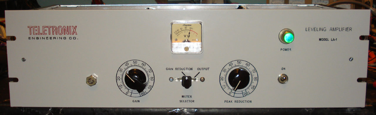
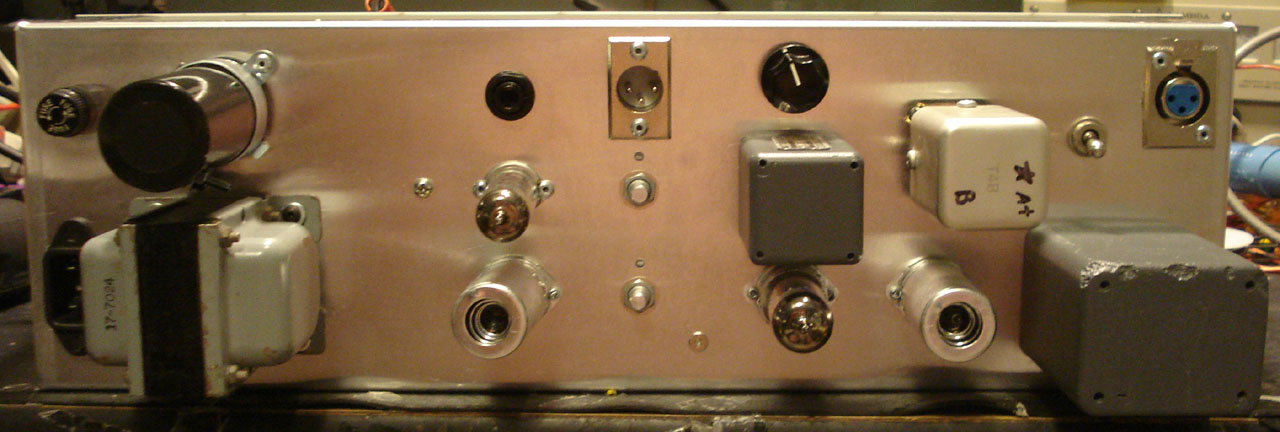
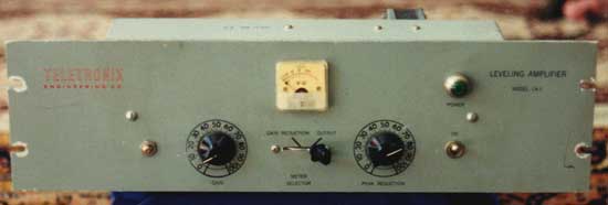
I just finished this project and wanted to show it off a little bit. Thought you might like to see the results.  I had one last set of original transformers (UTC HA-100X, A-24 and Triad R4A) and wanted to do something a little different than just another LA-2A clone, so I decided to go back to the beginning and make an LA-1 clone. I was able to find the original meter, meter switch, and power indicator lamp, and used vintage toggle switches for the Power and Comp/Limit switch (even though the original LA-1 didn't have that switch).  The Pièce de résistance is the original Teletronix T4A that I'm rebuilding and will use with this unit. I took some liberties to improve performance and usability, the Gain and Peak Reduction pots are Alps Blue Velvet, the output coupling cap is a Solen film cap, and many of the critical audio paths are shielded using Mogami wire, where in the original they were wired unshielded.  And the electrolytic caps are all modern, of course. Still a little tweaking to do, but it's about 99% of the way there now.
Teletronix_LA-1_Front-2.jpg

Teletronix_LA-1_Rear-2.jpg
 
Wow, that looks amazing - great work!

So this would have been a pre-1968 piece of equipment?  What are the differences between this and the LA-2A?
 
Yes, this would have been 1960 - 1964 time period, I'm guessing.  I couldn't find a schematic for an LA-1 so I built it to the LA-2A 1968 schematic, which is my favorite. The only substantive differences I know of are that the LA-1 didn't have the Comp/Limit switch, and the early LA-2A's have different values for the plate and cathode resistors on the 6AQ5A, which gives it more gain, and is actually less desirable. Also, it probably didn't have a Stereo Adjust pot.  If anybody has any more info on the LA-1, please post it here!

Joe


letterbeacon said:
Wow, that looks amazing - great work!

So this would have been a pre-1968 piece of equipment?  What are the differences between this and the LA-2A?
 
The meter switch?  From an old intercom switch panel I bought at a surplus sale years ago.  They sat in a box for years and then I discovered they're the exact part for this project. Same with the power lamp socket.  Some times it pays to be a pack rat.

Joe

rooster21 said:
Beautiful work!

Where did you source the switch from?
 
Thanks for the good words. It can't be a 2U rack because of the location of the rack screw holes.  The aspect ratio of that image is slightly askew.  This is actually one of the pics I used to build my clone, but I think there's a better pic of the front of the unit out there somewhere.  Anyway, I imported the image into CorelDraw and drew a grid with 1" spacing over the top of it. I knew the unit was 19" wide, so I could base everything else off that. It's definitely a 3U box.

Joe

dissonantstring said:
very nice build joe! 
i'm sure it's my imagination, but why does the image of the original that keef posted look like a 2U rack?  is it?
 
Thanks again for the good words.  I went by the LA-2A 1968 circuit, so technically this only looks like an LA-1.  I would have considered building the LA-1 circuit if I could have found any documentation on it.  If such documentation ever does surface, I'll build another one in a heartbeat.

Joe
 
Since it past so much time...
Was anyone successful in finding the schematics for the LA-1 ?  ::)
 

Latest posts

Back
Top