THAT compressor

GroupDIY Audio Forum

Help Support GroupDIY Audio Forum:

This site may earn a commission from merchant affiliate links, including eBay, Amazon, and others.

audio2

Active member
Joined
Jun 22, 2007
Messages
35
Location
Hollywood
Well first off i'd like to say im very glad to be a part of this forum. It took me months to register for some reason or something.?. So thanks to Wayne and Ethan for helping me out.

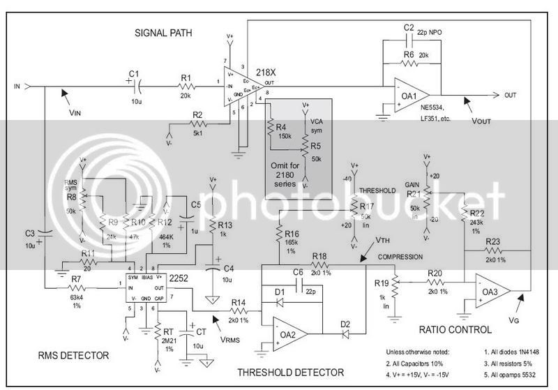
So i designed this compressor, i call the "Mini6", from the THAT application note AN100. Basically it uses the THAT2252 rms detector and the THAT2180 Vca. I have already etched a board but something was wrong cause the 2252 would get hot to touch. I think i found the problem, while getting it ready before posting i noticed a spot where ground was cut off from the rest of the board.
So i was hoping to get some board reviews, and input. Basically need some of the pro's to see if i missed anything.
If anyone is interested in making this compressor i will post the .brd files.

thanks
mini6.jpg
[/img]
basiccompschematic.jpg
[/img]
 
ahh, the .sch file... Well i just designed it off the schematic from AN100 but i can make one up in eagle in next couple days.
 
So i was hoping to get some board reviews, and input. Basically need some of the pro's to see if i missed anything.

it is a two side board? or where is the op amps supply voltage?

maybe you can add some caps for decouple the power supply, near of the op amps pins.
 
they should be powered, OA1 and OA3 are gain stages and OA2 is a precision rectifier it use feedback to reduce the 0.7 V drop of silicon diodes.


I´ve never seen an application of opamps without power supply.
 
other point is that you are using NE5532 and they are double op amps so you can use only one NE5532. if you don´t use a op amp on a dual op amp IC is a good practice connect to ground the + input and connect the output to the - input.
 
good idea i didnt think of that. i should've.
as for an opamp not using power what about as a servo, or dc output control loop?
 
they need power supply.
if you want that any kind of signal happens through an op amp, the signal must be between the values of polarization of the op amp (or you will have distortion).

on some schematics with op amps the power supply is omited, is not a good practice I think.
 
[quote author="12afael"]they need power supply.
if you want that any kind of signal happens through an op amp, the signal must be between the values of polarization of the op amp (or you will have distortion).

on some schematics with op amps the power supply is omited, is not a good practice I think.[/quote]

i guess im confused then. the schema shows the output of 2180 (pin8) going to the (-)pin on opamp 1. (+)pin to ground. It shows no power connection. Maybe you can help me understand this.
 
[quote author="audio2"]
i guess im confused then. the schema shows the output of 2180 (pin8) going to the (-)pin on opamp 1. (+)pin to ground. It shows no power connection. Maybe you can help me understand this.[/quote]

Opamps have + and - signal inputs AND + and - power inputs. The power inputs are usually drawn on the top and the bottom of the opamp and are sometimes not shown. Opamps won't pass any signal when there's no power connection. That's why people take the power connection for granted and often leave it out to "simplify" the schematic.

If you see an opamp anywhere in a schematic without V+ and V- connected to anything you can assume they should be connected directly to the psu + and -. Sometimes people even leave out small capacitors to ground that should be added near the opamps to smooth the psu-lines.
 
[quote author="Mendelt"]Sometimes people even leave out small capacitors to ground that should be added near the opamps to smooth the psu-lines.[/quote]

yeah, read the opamps data sheet. Usually it will specify .1u or 1u from +V to ground and -V to ground. Something like this

pwr.gif
 
The missing opamp power pins error should have been reported by the Eagle Electrical Rule Check function (labeled "Erc" button in board editor tools)
 
cool tip!

I've been making custom libraries, with the power pins as their own symbol as shown in the pic posted earlier. Before I did that, the voltage symbol I used wouldn't match the designated V+ or V- name given to some op amp pins.
 

Latest posts

Back
Top