The official G9 help thread

GroupDIY Audio Forum

Help Support GroupDIY Audio Forum:

This site may earn a commission from merchant affiliate links, including eBay, Amazon, and others.
Hey, Allentown is right in my backyard, I'm in Bethlehem! Shoot me a PM if you want.

Anyway, I did see the diagrams (which are great). I'll go with the Amveco's since you've had no issue.

Am I correct in thinking that you only need a current-limiting resistor when using an LED for the front panel indicator?
 
[quote author="riggler"]
Am I correct in thinking that you only need a current-limiting resistor when using an LED for the front panel indicator?[/quote]


Yes, a 1K or 2.2K rated at 1W should do it. I don't have the unit in front of me right now, but I think I used a 1K.

Just attach it in series with the anode. There's a detailed picture of what I did on my site.

http://www.zerrohouseproductions.com/preamps.html
 
Thanks! :sam:

Let's have an A-B-E meeting of the G9's. Mine should be done in a few weeks.

BTW -- your link should be zhppreamps, not preamps, in case anyone else is ineterested in seeing Curt's build.

-Damian
 
[quote author="gyraf"][quote author="CurtZHP"]Oops![/quote]

Take care. Remember that the G9 circuit is dangerous when powered..! Very little room for Oops'es..


Jakob E.[/quote]


Yes, but my website has yet to kill anyone. :wink:
 
Hi
So the world has seen yet another G9 preamp, or half of it anyway.
Channel 1 is dead. Channel 2 sounds and works wonderfully, with and without 48v (and DI) and is deadquiet. Got 245V at the rail, and a lot of other values wich I won´t bother you with now.
Here´s the thing: The output pot only shows 5Kohm??? when soldered but when desolvered it shows as should around 50 Kohm. Got 48 V at the input as well on channel 1. Any suggestions?
Thanks Jakob for a wonderful preamp...recorded some acoustic guitar with AKG c1000s today and it sounds soooo good, really.
best regards
Leif
 
It sounds like your supply rails are healthy, and that's half the battle. Can you try it with another 50K pot? It could be that you have a bad one. Also check for solder bridges on the control PCB for that channel. One other thing....
Check back a few posts on this thread to read about my misadventures when firing mine up for the first time. I had a very similar problem, with one channel being dead, and it turned out I forgot to completely solder in the phase switch.

Take heart. If one channel works great, and it didn't burst into flames on you, it'll be something simple.
 
[quote author="Leffe111"]
Here´s the thing: The output pot only shows 5Kohm??? when soldered but when desolvered it shows as should around 50 Kohm. Got 48 V at the input as well on channel 1. Any suggestions?
[/quote]

I haven't finished mine yet but.. I don't think the pot is broken. Does it "change" resistance when you turn the 12 pos gain switch? Lock at the schematic. Could it be that you had the lo cut filter in when you measured on the other channel? (Assuming the working channel showed 50K on the pot..)
 
Hi Guys,

I'm finally getting back to my G9 which I started a year and half ago! Not much time for DIY these days :sad:

I had a custom trafo wound with 15V, 220V and 48VAC secondary windings. The 220VAC unloaded is putting out 245VAC, which I hope will be ok once rectified.

The questions now is the 48V (unloaded putting out 47.5VAC) winding. Rather than get a another 15VAC winding and use the voltage tripler I thought I could just use a 48VAC rail to power the +48V rail.

It is safe to assume the only 'mod' I would have to do is omit some of the diodes/caps? Looking at the schematic we are wanting to hit around 60VAC before rectification. What would be the safest/best way to do this?

g9_psu.gif


Jakob mentioned this a few pages back:

You'd want something like 50V/30mA for the 48V phantom power (and change the phantom power circuit accordingly)

Jakob E.

But we didn't get into details of how/what should be done, so at least this will clear it up for future builders.

Thanks in advance!

Matt
 
Matt,

I think that you're going to have to build a bridge rectifier to replace the voltage tripler. I think that you could get away with copying the 220V bridge rectifier seen in the schematic right above the 15V tripler.

But you're going to have to filter it picking the schematic back up around zener diode D6. Definitely will still need T1. I'm not the guy to best answer this, but from what I can see this is a good starting point.

Kudos on getting your G9 going, I'm in the same boat, took quite a while to get moving. :green:

BTW -- another question. I had some old Sprague Atoms to use for C14 and C15. Well, they're too old and I don't trust them. So I bought from Mouser 2 Nichicon 150uF 350V UPB2V151MHD. (Low Impedance Aluminum Electrolytic Capacitors - 105 Degree 350V 150uF 18X40 20%Tol 7.5LS 105Deg)

They're a LOT smaller than the Atoms I had... they going to be okay?

:?:
 
Ok,

So here it is, the updated power supply for the G9 using a 42V winding in place of the 15V if you are going to use a single custom wound trafo.

G9_modded_psu.gif


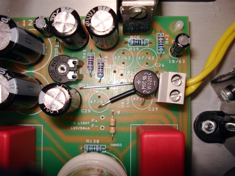
Note when compared to the original schematic parts D8 - D12, C26 - C29 are omitted and C20-22 need to have their voltage rating upped to 100V as 42V full wave rectified is doing to push you over the 63V tolerance.

You can cleanly do this with a bridge rectifier. I used a W02, but an 01 would have worked as well and then moved the legs around and lined it up on the PCB to make a neat fix. I added heatshrink on the - leg which goes to ground just incase it shorted with one of the AC junctions.

The results look like this:

G9_48V_Mod_Comp.jpg


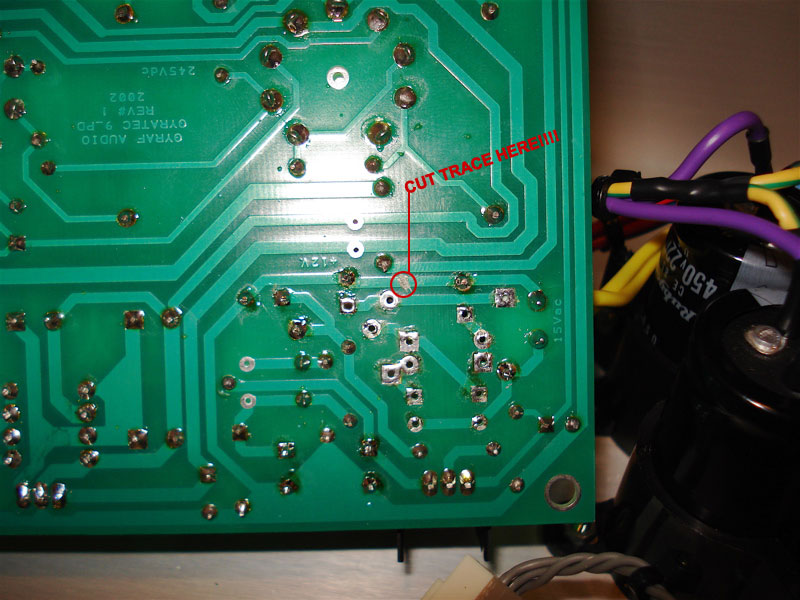
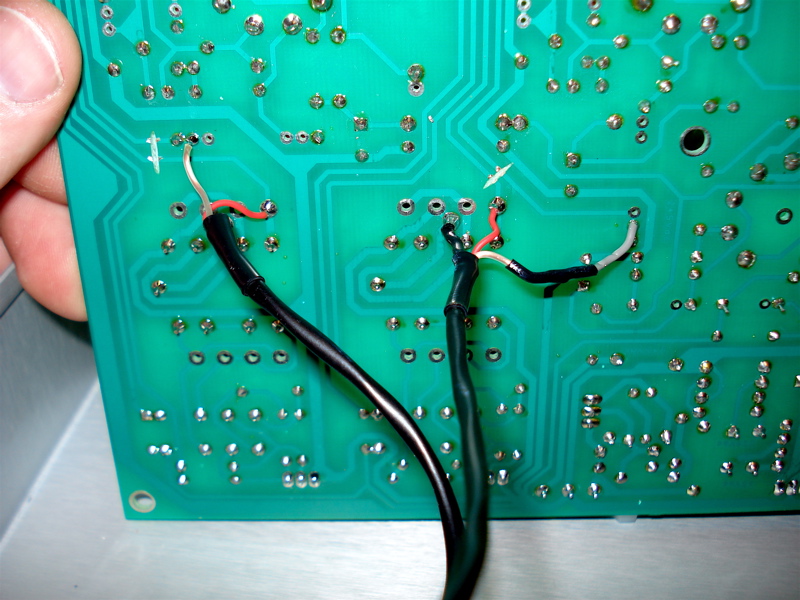
Not in order to do this I needed to cut a trace under the board because one of the AC connections was also on the ground trace, I did like this:

G9_48V_Mod_Traces.jpg


Just for the record these are the specs of the torrid I had wound:

Prim1 : 230v
Sec 1: 220v @ 75mA
Sec 2: 15v @ 1.5A
Sec 3: 42v @ 50mA

Come to 42VA, but I just had them make up a 50VA.


While on useful info and since I had my camera handy, here is another tidbit:

DI/INSTRUMENT MOD:

This has been brought up in the past but a couple builders have experienced problems with oscillation at the highest gain settings and forum user AXEL offered a solution to the problem that seems to cure it here: http://www.groupdiy.com/index.php?topic=114787

Jakob has a detailed drawing of this on his site here: http://www.gyraf.dk/gy_pd/g9/G9-EDIT.GIF

But I thought it might be nice to shoot a of the mod done so you can see it on the actual PCB.

G9_DI_Mod.jpg


You can see where the traces have been cut, I used a small cutting wheel with my Dremel drill and it did the job just fine.

Riggler,

RE your caps, they should be fine. If you look a few pages back you will see that I have shown the Rubycon brand version of your Nichicon. Jakob confirmed they will be fine and I think Godders used the same ones in his circuit... caps have come done in size over the years as have many other components.

Cheers

Matt
 
That looks about right Matt! Nice drawing!

:cool:

And thanks for answering my cap question. Now I just found the slickest little meters that fit exactly into the open area above the line/mic & phase switches.

The AL15 is 1.4" square, vintage look, and is a perfect fit! A cool TV guy I worked with pointed these out to me and I thought I'd pass it along. I wonder if Jakob planned for this when laying out the front panel PCBs.

http://www.sifammeters.com/Audio_Level/AL15_Retro.htm

I am not going to add these to my G9, but maybe in the future. My DAW gives me a good reading, so I really don't need them.
 
I have some problems with my G9.

It has been running a whole year without problems but suddenly the 48v powersupply roasted and after 3 month the 15v trafo died. I took it apart and replaced everything in the 48v powersupply, the roested trafo and now it works okay. The trafo I replaced it with is only a 25VA and now it gets really hot.

My question is: Is the new trafo undersized? and could there be some problems in the circuit that also would have roasted the old one?

Best regards
Soeren - Denmark
 
If I had to take a wild guess, I'd say that maybe the original 48V supply had either a shorted diode, or maybe the regulator (TIP121) went bad. The resulting excessive current could have sufficiently damaged the transformer to the point that it died when it did.

You could certainly stand a bigger transformer in terms of VA. It certainly wouldn't hurt.
 
How's the voltage regulator? Not just the phantom, but also B+?
Are their heatsinks getting very hot?

If your power transformer is getting hot, then you are asking too much of it, so it is either undersized (G9 calls for 30va I believe), or a fault is drawing too much.

Have you checked voltages? On the PCB, there are several handy spots for this, just be careful.

Also, I would carefully look at caps, especially C14 and C15. They bulging, oozing, or anything?
 
[quote author="riggler"]How's the voltage regulator? Not just the phantom, but also B+?
Are their heatsinks getting very hot?

If your power transformer is getting hot, then you are asking too much of it, so it is either undersized (G9 calls for 30va I believe), or a fault is drawing too much.

Have you checked voltages? On the PCB, there are several handy spots for this, just be careful.

Also, I would carefully look at caps, especially C14 and C15. They bulging, oozing, or anything?[/quote]
I thought the same with the 30VA.
I have asked around and no one have ever heard about a trafo could die just that so have a suspicion maybe some other thing could be wrong.

I checked my voltages:
C14: 361v
C15: 239,3v
Heater: 11,55v

The trafo with 220vac gives 286vac and the 15vac is instead 17,65vac.

Is there other voltages I should check.
Also the caps looks just fine. Nothing that shows any problems.

The 12v regulator is mounted on the surface on the bottom plate electric separate. It get very hot,
The 245+ HT is mounted with a heatsink and also gets very hot.

Best regards
Soeren - Denmark
 
[quote author="ognam2"]why does my g9 loose all the gain at the 12 Position of the Gain Switch?
Thanx Jonas[/quote]

It's oscillating. Search here for more info.

-Chris
 

Latest posts

Back
Top