The official G9 help thread

GroupDIY Audio Forum

Help Support GroupDIY Audio Forum:

This site may earn a commission from merchant affiliate links, including eBay, Amazon, and others.
Harpo said:
aclac said:
If you or somebody have some ideas, please let me know. Aclac
Maybe you placed the end stop washer when the lorlin was not set to its full ccw position. Lorlin now switching between positions 2/3 instead of 1/2.

Oh, I don't have any end stop washer and all pos is allowed  :eek:. Btw, there is short circuit (outputpin 2 and 3 are connected together by..)?
 
flintan said:
And you have of course triple checked that the wiring of the switch is correct?

Thanks for this, but no reason, because it work well other way (+ pos). Maybe I should screw out control PCB and try find something small parts of wiring between the lorlin legs or somewhere. I don't like solve out SW, because it is too messy and too risky to broke PCB. Hmm, this function is not so important to me, and I can live without it. Other channel work well anyway.
 
My problem solved:

Didn't have gain and about 6db lowpass all the way - Output didn't have ground reference

G9 was fine, my soundcard unbalanced inputs had trs-sockets and ring was not connected anywere ;)
 
tmuikku said:
my soundcard unbalanced inputs had trs-sockets and ring was not connected anywere ;)

HAHAA, I bought powerful old PA amp and there is XLR connections and cold- pin was without wire. Some kind "joke" maybe, because there is big label that "balanced input"... Made in england.
 
Hello guys
I was thinking of exchanging my OEP input transformers for some Pikatron. I saw some RÜP 817M/1 on ebay and they state a  1: 3,21 + 3,21 ratio (thus 1/6.4).
would this work ? any experiences?
maxime

 
I was making finishing touch to my G9 but there was 100hz and harmonics peaking -66 dBs and I found this thread: http://www.groupdiy.com/index.php?topic=32559.0

I did the same thing: moved the whole B+ supply to separate board and 100hz hum dissappeared totally (now only 50Hz hum peaking about -95)! well worth doing!
 
Just looking over the schematic for the G9. Is there any particular reason why the second transformer needs to be rated for 30VA? That seems like insane overkill to me, considering that it only has to supply the current for the tubes, which is in the 10s of mA at most. Seems you could save money and space with a torroid rated for much lower output.
 
The same-rating specified for the second transformer is because smaller transformers behaves very unpredictable in reverse configuration (because of bigger copper loss). Smaller transformer does not save much money anyway, and we have plenty space.

So it's about ease of building - you can always experiment with smaller types yourself, it's just not "plug-and-play"

But be aware that smaller non-toroid transformers do induce a lot of electromagnetic interference.

Jakob E.
 
gyraf said:
The same-rating specified for the second transformer is because smaller transformers behaves very unpredictable in reverse configuration (because of bigger copper loss). Smaller transformer does not save much money anyway, and we have plenty space.

So it's about ease of building - you can always experiment with smaller types yourself, it's just not "plug-and-play"

But be aware that smaller non-toroid transformers do induce a lot of electromagnetic interference.

Jakob E.

thanks for the clarification. I figured it was something like this.

mason
 
tmuikku said:
I was making finishing touch to my G9 but there was 100hz and harmonics peaking -66 dBs and I found this thread: http://www.groupdiy.com/index.php?topic=32559.0

I did the same thing: moved the whole B+ supply to separate board and 100hz hum dissappeared totally (now only 50Hz hum peaking about -95)! well worth doing!
Thanks for the hint. I'm definitely going to have a go at this. I spent quite a bit of time looking for the source of 100Hz and harmonics at around -66dB: just the electronic engineer in me wanted it to be better although you couldn't hear the hum at all. It was definitely something from within the box and presumably the (rectified) power supply that was producing the 100Hz and harmonics, but I couldn't figure out how it was coupling into the rest of the G9. I tried the 48V supply (wasn't that) and suspected the transformers and heater current but couldn't prove it. Veroboard should arrive in a few days so then I can try an exact comparison of having the HT supply components mounted on and off board without altering anything else. (I have spare HT components so I can test in situ without moving any transformers or caps or other things) I'll post a screen shot of the two noise spectra once I've done that.
 
tmuikku said:
I was making finishing touch to my G9 but there was 100hz and harmonics peaking -66 dBs and I found this thread: http://www.groupdiy.com/index.php?topic=32559.0

I did the same thing: moved the whole B+ supply to separate board and 100hz hum dissappeared totally (now only 50Hz hum peaking about -95)! well worth doing!
Good work!

I lashed up a really rough external PSU from the same component values as the on-board-PSU of the G9 on a piece of tag board. It really was rough: no screening. No careful soldering. Nothing. Just hanging out the back of my G9 box on long flying leads. I then hooked this up to the existing internal power transformers and removed the HT link on the G9 board next to the internal regulator and hooked the external supply in there. So if there was any RF pick up due to long leads or layout, you'd expect it to be much worse with the external supply....

I tested the PSU under load i.e it was amplifying pretty heavily on one channel, whilst the other channel was quiet.

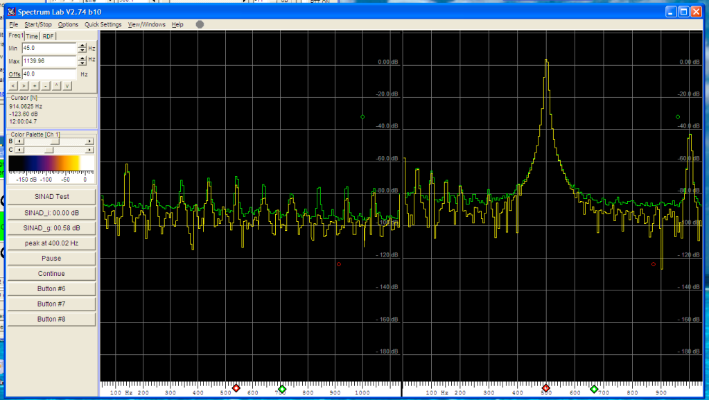
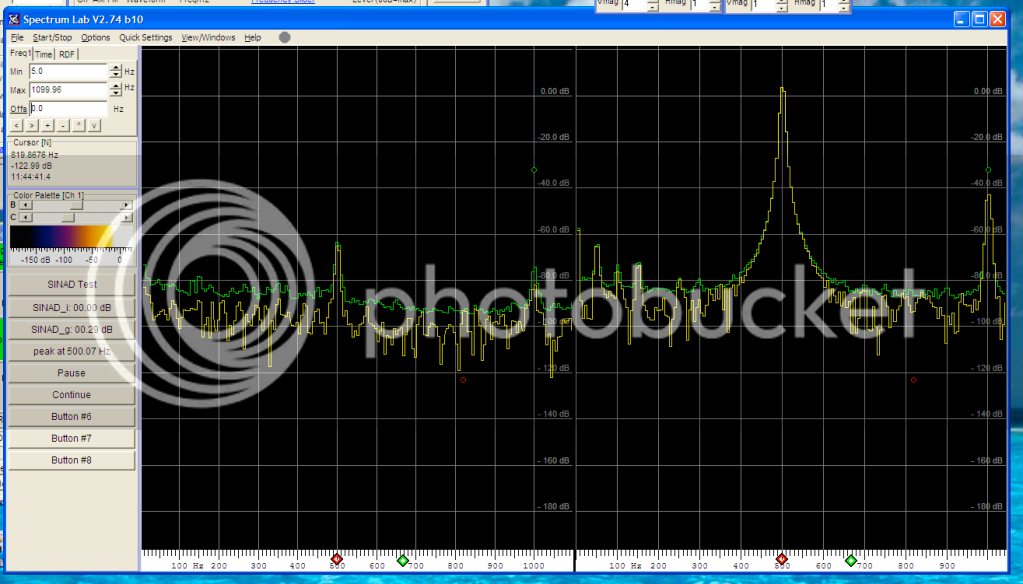
The spectrum chart shows both left & right channels from 0 to 1100Hz. Left = quiet. Right = high signal.

Test 1 =
internal PSU circuit powered from original transformers mounted in the box
+4dBm output on right channel @500Hz test tone (approx -25 dBm in from an unmatched low Z sound card output to right hand channel)
left channel 0 input (terminated with mic impedance)
gain set to approx 60% on all knobs.
4dbm-on-right-mic-impedance-on-left-internal-supply-Screenshot2010-07-23at115908.png


Test 2 =
External PSU circuit powered from original transformers mounted in the box
+4dBm output on right channel @500Hz test tone (approx -25 dBm in from an unmatched low Z sound card output to right hand channel)
left channel 0 input (terminated with mic impedance)
gain set to approx 60% on all knobs.

4dbm-on-right-mic-impedance-on-left-external-supply-Screenshot2010-07-23at114345.png


Thus the only difference was the physical location of the HT diode rectifier, HT regulator, off-board capacitors & resistors.

You can see on test 1 that there is some 100Hz and it's harmonics on both channels. It wasn't that high and I could put up with it.
But on test 2 the 100Hz on the left channel almost disappears. The small 500Hz peak that is left is almost certainly cross-channel cross-talk (and could be my test set up to be honest).

As they say on TV: MYTH CONFIRMED. There is 100Hz hum and its harmonics injected into the G9 output that can be avoided via use of a simple external PSU board without changing the circuit design.
 
i've been meaning to post this for a while...

about a year ago i fixed the niggly little hum problem in my two G9's in a similar way. i made some little external boards with the rectifier, caps and a zener+mosfet pass "pre-regulator" which then fed smoothed DC into the normal G9 regulator.

the difference was dramatic. it went from a quiet, but noticeable and annoying hum level (harmonics of the line frequency), to completely NO discernible hum at all above the noise floor. i have scope shots and audio recordings of before and after the mod. if people are interested i can post what i did.

perhaps for some units the HV power supply recifier/caps etc are inducing ground currents that are being picked up in the preamp stage?
 
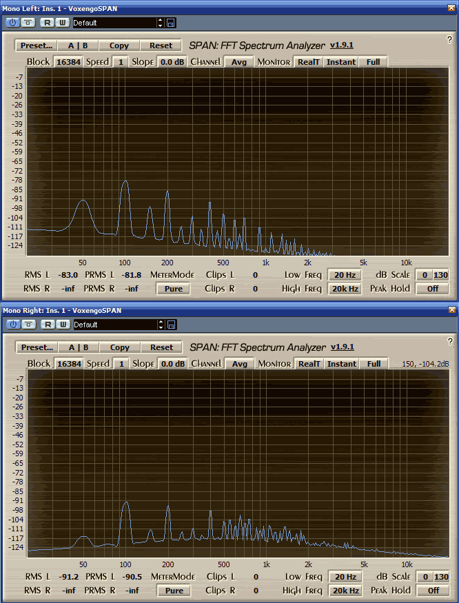
I'm pretty sure every single build with the usual G9 PCB has this 100hz hum + harmonics problem. It's just that for most people it's either good enough, they haven't noticed it, or they haven't any means for measuring it. Only the B+ bridge rectifier causes this problem by the way. Heater rectifier does not pollute the grounds. In fact, just moving the B+ bridge rectifier and the first RC stage out of the PCB should fix the problem.

See all the harmonics from 100hz and above:

edcorandlundahlhum.png


They will be completely removed. I didn't even bother grabbing a screenshot of the fix. There's simply no trace of the harmonics, just a straight line.

I later also removed that 50hz peak by shielding the PSU transformers.

PS. in the above image we see the harmonics with edcor XSM10k/600 and the standard lundahl output transformer. The bass cut due to the too high output impedance of the output gain stage is clearly visible on the lower lundahl screenshot, even on the noise floor. Unrelated to the rectifier harmonics problem of course.
 
i agree it's possible that many people either have not noticed this hum problem, or perhaps thought it's just an inevitable part of "the sound". my build it was quiet enough for me to use the pre on many recordings, for a couple of years - but eventually i decided to get to the bottom of it... glad i did.

after trying to kill the hum many ways, (shielding, moving transformers, changing ground paths on and off the pcb etc) i finally tried using an external HV supply jumped over from my hamptone preamp, and instantly the hum disappeared. what a relief that was!

now this was a while ago... i think i tired just moving the bridge rectifier and caps off board first, and from memory that didn't fix the problem, i'm pretty sure i had to do some regulation/smoothing off board first - but as i said it was a while ago so i might be wrong.


I am having some problems with my nearly finished G9 :)

I have only made 1 channel for now.. i will make the other one later.

The G9 Works, it has some oscilation which i have to try cutting the traces.

But my greatest problem, is that my G9, the output lvl, is REALLY weak. To understand how weak it is, i will say this... i have to give all gain from my Profire 610, to have a subtle sound, which is approx, 40db, which i normallize and get a distorted sound with a little of noise.

I am using 2 Marshall 12ax7 for now, since i used the ones from my marshall.

If i set the gain to max, it oscilates, so with this, i know the first stage of gain is as it should be. So... is the problem the Phase inverter? Maybe because its a 12ax7 instead of an 12au7? The tubes are both working, i have tested them already, swapped position and they work in my marshall. Is there anything that can be causing this? i will be buying some 12au7 this days, but maybe its not the problem.

I really appreciate your answers :) i am not allknown about electronics, but i understand some basic things.. this is my third project so i am really glad i could make it at this point :)

As always, sorry for my english, its not my primary language.

And Thanks jakob for sharing this great project!
 
12AX7 is probably partly to blame for the oscillation - it's a much higher mu tube than the 12AU7.

you might still have oscillation problems when you swap in the 12AU7 - but that can usually be fixed by the "cut traces & run shielded cable to and from DI jack" mod.

the low level/distorted output could be:

- to do the 12AX7 substitution, or
- how you connect your G9 to your profire 610 - are you connecting to an unbalanced 1/4" input? where are three pins of the G9 output XLR going?
- or something else  :-\

BTW, there's no "phase inverter" in the traditional guitar amp sense - only the "input stage" and "output stage"
 
haima said:
12AX7 is probably partly to blame for the oscillation - it's a much higher mu tube than the 12AU7.

you might still have oscillation problems when you swap in the 12AU7 - but that can usually be fixed by the "cut traces & run shielded cable to and from DI jack" mod.

the low level/distorted output could be:

- to do the 12AX7 substitution, or
- how you connect your G9 to your profire 610 - are you connecting to an unbalanced 1/4" input? where are three pins of the G9 output XLR going?
- or something else  :-\

BTW, there's no "phase inverter" in the traditional guitar amp sense - only the "input stage" and "output stage"

Thanks Haima, the 3 pins of the xlr connector are going to the preamp input of the profire through an xlr-xlr balanced cable.

I will try these days, buyin 2 12au7, to see if the problems are solved. I hope this is the problem and not any other thing.

If there could be any other thing, how should i debug the preamp in that case?

Edit: Could it be that the output transformer has any problem and its deliverying a very low lvl?

Thanks :)

Sorry, if i am not clear..

The questions are:
1) Could it be that the 12Ax7 are delivering SO low output? that has to be add like 80dbs(60db+normalize)
2) Maybe.. the output transformer? should i take the input to a standart plug and check if the lvl is allright? or should i check the primarys of the a2e?
 
Back
Top