The official G9 help thread

GroupDIY Audio Forum

Help Support GroupDIY Audio Forum:

This site may earn a commission from merchant affiliate links, including eBay, Amazon, and others.
phelar said:
Hi again.
I got some new questions. How do i messure the preamps noice level in a proper way? When i got the g9 knobs turned down and the input gain on my mbox1 turned down i read -105db at 100hz and -110db at 200hz. This is with a dynamic mic on the input. How do i make a 200 ohm dummy load and exactly how do i connect it to the input. I want to compare readings with other g9´s.
I dont really know where to turn the gain knob on my mbox1 to get fair readings :-[.

A dummy source is one that has the same impedance as an expected source.
This could be as simple as a 200R resistor soldered between pins 2 & 3 on an XLR plug.
You plug it in instead of a dynamic mic.

A dummy load is one that has the same impedance as an expected load.
This could be as simple as a 600R resistor soldered between pins 2 & 3 on an XLR socket.
You plug it in instead of your real terminated load. [although not many studios bother to terminate their 600 ohm busses nowadays]

First you need to do is calibrate your audio interface and measuring equipment to the real World.

One way of doing this is to output a known sine wave from your DAW test signal generator at around 50Hz into a 600R dummy load. Now measure the voltage between pins 2 & 3 of the XLR cable with an AC multimeter and adjust your DAW test signal generator level until it reads 776mV volts RMS (or there abouts). This level on the DAW is 0dBm. +4dBm [4 dB higher than that level on the DAW] should measure around 1.228V. If you have a better quality multimeter [True RMS], or an oscilloscope, you can use a higher frequency for calibration.

Now you need to see what level this generates on your audio input: loop your output to your input with a physical patch cable on your audio interface. Set the DAW output level to output your +4dBm sine. Set your audio input pads off and the input gain trim on the audio interface to 0dB. What does your DAW input meter read? It may not read the same as the DAW output, as input dBFS sensitivity does not always match output dBFS!

In my particular DAW and for my particular audio interface I know that a -11dBFS test signal generator app in logic connected to a line level output channel corresponds to +4.47dBm in the real world (1.296V). But this results in -14dBFS measured in the Logic Multimeter app on a line level input channel via an external physical loopback patch. So there's a "hidden" 3dB of loss in my interface.


There are many ways of measuring noise. Perhaps the most important ones if you're concerned about your PSU performance are:

1. Basic maximum gain of your G9. Loopback your audio interface using a patch cable. Adjust the output for something around -60dB FS sine or if you've calibrated your audio interface -60dBm [in my case that's -71dBFS]. Check the input level (remember, it may not be 60dB FS due to some internal system gain or difference between input and output sensitivity). That's not so important. Now replace the loopback patch with your G9 with maximum gain. Measure the input level now, and how much more level there is on maximum gain with the same test tone compared to before.

2. EIN (equivalent input noise) = a terminated dummy source and gain turned to max. & measure the noise floor on the audio interface input relative to dBFS. Add the maximum gain of the G9 you measured in 1. Subtract the level in your DAW corresponding to your nominal level of +4dBm on the input [-14 in my case].

3. Cross talk = a terminated quiet input on one channel. Set up a known test tone on the other channel at reference level e.g. +4dBm out. Measure the amount of test tone present on the "quiet" channel. Note this is frequency dependent. Yo can also set up a pink noise generator on one channel, and then you will see how good your PSU filtering/ inter channel isolation really is at all frequencies.

Less important (as you probably want a bit of color in a tube amp)
4. Intermodulation distortion = insert two sine tone generators on one channel e.g. 1Khz and 1.5Khz and measure the amount of intermodulation products (500 Hz, 2.5Khz, 3.5Khz, 4.5KHz etc) on the output relative to the 1Khz and 1.5Khz test tones.

There's a pretty good note here: http://www.rane.com/note145.html explaining the different types.

 
Thank you!
I really get what you are saying:) I´ll start working on it tomorrow. 
"Set your audio input pads off and the input gain trim on the audio interface to 0dB" As i don´t have a unity mark (0db on the input gain trim) i´ll turn it up just before the peak led on the mbox (audio interface) is lit, is that right?

Thanks for your answer! It was really nice of you to take the time to help me.
 
phelar said:
Thank you!
I really get what you are saying:) I´ll start working on it tomorrow. 
"Set your audio input pads off and the input gain trim on the audio interface to 0dB" As i don´t have a unity mark (0db on the input gain trim) i´ll turn it up just before the peak led on the mbox (audio interface) is lit, is that right?

Thanks for your answer! It was really nice of you to take the time to help me.
No. Normally there'll be a gain trim control somewhere on the line-in interface. Adjust this for 0dB = unity gain on the input amplifier on the audio interface. Not for 0dBFS level.... If you can't do this via a calibrated (software) setting, then adjust your input channel gain trim on the audio interface so that the input and output channel in the DAW measurements read the same level with your physical loopback patch cable inserted between input and output, and a +4dBm test tone being output from the DAW signal generator.
 
gyraf said:
In general, I won't recommend substituting the LL5402 in the G9 output circuit. It works pretty well, and few others will do the job as good without changes to the circuit (specially output capacitor value).

That said: if you want, go ahead and try it - let us know how it turns out.

Jakob E.

I tried it.  The low end is fine with the 4u7 output capacitor all the way down to 20Hz.  But the high end starts to roll off early (decline begins at 2k and is down 12db at 10K!  I guess the issue is that it has plenty of inductance but too much capacitance between the multifilar windings for the high output impedance, does that sound right?.  The LL5402 works fine I tried it, so I wonder if the LL5402 is a layered winding (specs don't say)?

I tried the OEP too, but it doesn't handle the low end.
 
Bruce, you're obviously running into inter-winding capacitance.

Quad-filar is one of the simplest and cheapest ways to wind a transformer - and nice enough for API-style outputs, driven from a very-low source impedance, where interwinding capacitance will actually help keeping top-end up (if transformer is wired correctly).

And yes, the LL5402 is layered, reverse-wound and full of nearly all the tricks of the trade.

Jakob E.
 
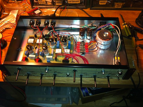
On a related note to the above post on noise I'm looking for a confirmation on my sanity - or lack thereof.  I've got my new G9 passing audio and seemingly working fine but have some hum which seems to be a fairly common issue with this guy.  Mostly in channel 2.  After messing around with grounding schemes I finally pulled the toroids and started moving them around.  Initially they were in a fairly standard location (see pic).  I turned them sideways and 45 degrees and cured 90+ percent of the hum issue.  I'm just surprised as it doesn't seem like transformer location was that much of a problem with other units from doing a search in the forum.  Could there be something in addition that I'm missing?  Measurements of ripple appear to be in the "safe zone".

8465677679_c2e22506d1.jpg
 
There may have been other problems reported here, but on a correct build the positioning of the power transformers is by far the most important parameter for getting hum down below noise.

If your problem persists, try putting in a grounded shield between your power distribution block and the wires going to/from ch2 front-panel controls.

Jakob E.
 
I have noted that other people have mentioned that 4th click pop. The first time I turn past the 4th click I get a pop, after that it goes away. Is there some high value leak or bleed resistor that can fix that or is that just an artifact of the gain structure?

Anybody know?
 
A 1M+ R to 0v from the switch side of the 100k R at step 4 would likely help...but you are leagues more ambitious than I so let us know.
 
shabtek said:
A 1M+ R to 0v from the switch side of the 100k R at step 4 would likely help... so let us know.

There is already R12 which should leak any charge from that point to ground, which makes me think the pop is not the 100K resistor coming into play, but instead something to do with the 82K becoming 1M (R27).  Maybe R27 should be smaller so the drop in attenuation is less.

But the problem is, I don't get why after turning the gain up past the pop, and then down, it doesn't pop the second time.

I am going to do some measurements.  I will let you know.
 
bruce0 said:
shabtek said:
A 1M+ R to 0v from the switch side of the 100k R at step 4 would likely help... so let us know.

There is already R12 which should leak any charge from that point to ground, which makes me think the pop is not the 100K resistor coming into play, but instead something to do with the 82K becoming 1M (R27).  Maybe R27 should be smaller so the drop in attenuation is less.

But the problem is, I don't get why after turning the gain up past the pop, and then down, it doesn't pop the second time.

I am going to do some measurements.  I will let you know.
I don't have this on my build.

The symptoms would suggest (significant) charge storage on a capacitor somewhere, that is then discharged once when moving the gain switch to step 5.
I was going to suggest checking R12 and R27 are properly connected to ground.
Or maybe something around C4/C5 is leaky? Flux?
Are you also using a "make before break" switch for SW2?
Maybe you can probe with a 10Meg scope for any DC offsets before and after the pop?
 
MeToo2 said:
Are you also using a "make before break" switch for SW2?
Maybe you can probe with a 10Meg scope for any DC offsets before and after the pop?

Yes... MBB but I modified BBM to make them that way, so maybe I screwed up.
Re: Probe prior... that is what I was planning, thanks
 
Hi guys,

I've two question about the G9: Can I mount directly the 78S12 on the case ?

And my second question is about grounding. Who go where ? Inputs pin 1 to star ground ? Main GND to star ground ? Jack's GND too ? That's all ? Or something from the PCB goes to the star ground ?

Thanks.
 
78S12 should be mounted electrically isolated from case(!!)

Grounding:

1) wire all xlr pins1 together - connect to one of their ground tabs. This ground tab is your star home.
2) wire IEC power ground to this point.
3) wire a connection from all other parts of your chassis to this point as well, unless you're sure they are already electrically connected.

3) wire from star home to 0/gnd on ONE of the 3-pin molex input connectors (the other just needs + and -) - this is the only point where your circuit ground meets chassis ground and mains 0V/Gnd.

4) For the jack/track modification, take ground for each front panel jack at the ground connection of the related input transformer.

Jakob E.
 
My G9 is done ! Sound really great !!! But only with mic/line, not with the DIs. I use normal wire for this and have noise. Need to use shielded wire between PCB & jacks or this is not the problem ?

But yesterday I use my G9 on a mix (bus master) and... Waow !!! Amazing !
http://soundcloud.com/justforyourears/jam-session-mix-with-g9

Jacob, many thanks for your work !!! Really easy project for newbies like me.
 
Congrats!

And yes, you should preferably use shielded cable between pcb and front panel jacks.

Also make sure to wire the front panel jacks correctly, this is a very common mistake.

Jakob E.
 
I think it's correct cause I've sound. I will change my wires to see.
The jacks are stereo but of course wired in mono. That can be a problem ?
 
Back
Top