ruffrecords
Well-known member
I have been asked many times if I am going to come up with a tube compressor design. I always planned to but never got round to it what with designing various EQs, mixers and so on. Then recently I was approached by a group member who thought he would like to use the Twin Line Amp from the EZTubeMixer project as the basis of an opto compressor like the LA2A. This was very much what I was thinking so I helped him out and as far as I know he's working away on it right now. So I thought it was about time to put pen to paper to sketch out the basic idea. There's a lot of detail to work out but I know the principle is sound having built something similar for a client at the end of last year.

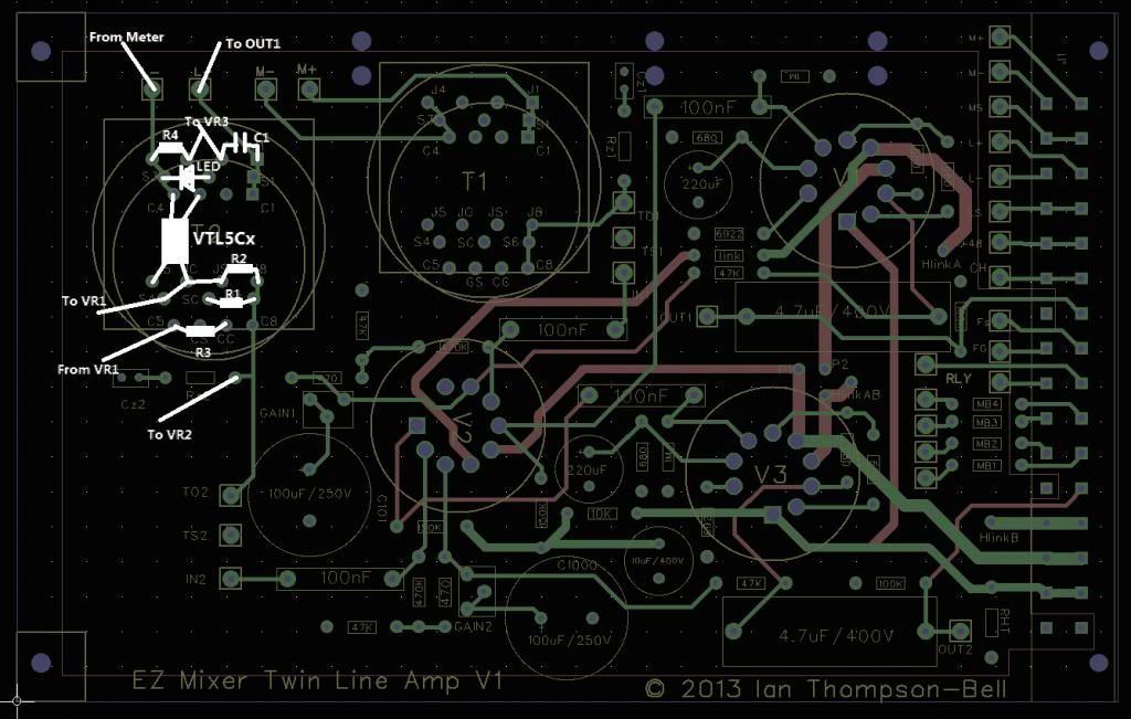
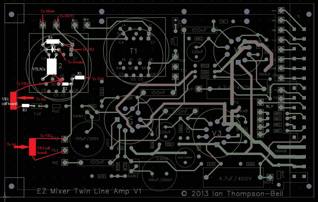
Referring to the the above block diagram, the signal passes through a 10K:10K transformer mounted on the TwinLineAmp (TLA) board then through a pot divider consisting of R1, R2 and the opto cell. The pot divider output goes via VR2 to one of the TLA amplifiers to the output. VR1 is the gain make up control and the intention of R3 is to set the zero position of VR1 to overall unity gain. S1 shorts out R2 to change from compression to limiting exactly as in the LA2A.
The side chain signal is taken from the junction of R1 and R2 to VR2 which is the threshold control. This sets the amount of compression applied to the signal. The output of VR2 is amplified by the second TLA amplifier and passes via C1 and R4 to the LED in the opto cell. A second LED is wired in the opposite polarity across the opto LED. This is necessary to prevent C1 and the opto LED acting as a simple charge pump. This second LED may or may not provide a useful indication of compression. R1 sets the LED current and may need to be altered depending on the chosen opto.
Gain reduction is roughly proportional to current through the LED so the gain reduction meter GR is set up to measure this current with VR3 setting the gain. With this set up there is no need for a meter zero adjustment.
I am fairly opto agnostic but in this topology the compression ratio, attack and decay times are determined largely by the opto so you need to think about the values you need. Also, the max and min resistance varies with opto type which affects the values of R1, R2, VR1 and VR2.
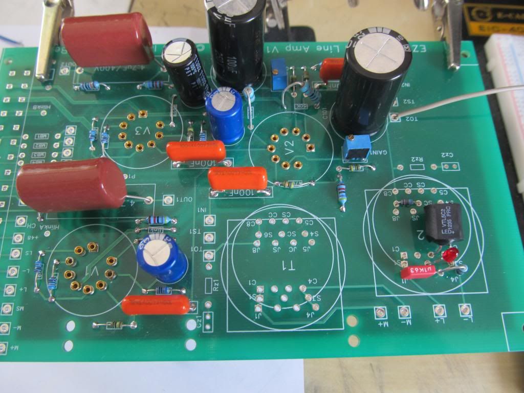
There is plenty of room on the TLA PCB to mount the opto and its associated components where the second input transformer would have been.
There are various enhancements you can consider such as using a pair of optos with their LEDs connected back to back so both halves of the signal are taken into account, or stereo linking.
Through this thread I am happy to support anyone who decides to build an opto compressor based on the TLA.
Comments, suggestion and questions are welcomed.
Cheers
Ian


