Two-Tube 'MILA-like' 6SN7 mic pre thoughts

GroupDIY Audio Forum

Help Support GroupDIY Audio Forum:

This site may earn a commission from merchant affiliate links, including eBay, Amazon, and others.

Matador

Well-known member
Joined
Feb 25, 2011
Messages
3,103
Location
Bay Area, California
I was looking over the schematic of the MILA preamp by NYD:  built with two 12AV7 tubes, with two cascaded voltage gain sections followed by a parallel-tube transformer driver, with adjustable feedback.

I was thinking this topology might be interesting to covert to a 6SN7, but I have run into a few issues so far.

Starting with the first two stages:  the first is a standard bypassed common-cathode gain stage with a 100K plate resistor, 200V plate voltage, and a 2.2K cathode resistor.  Standard calcs show this arrangement (assume a mu of 37 and plate resistance of about 6k) gives 31db of gain, an output impedance of about 5.5K, has an input P-P voltage swing of 4V and an output swing of about 140V peak-to-peak.

Here's the load line:

12AV7_bias.jpg


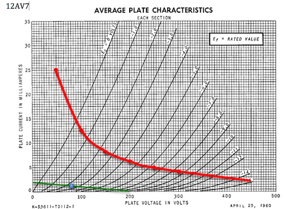
First thing, is that this seems like a very 'cold' bias point, down near the bottom of the curves.  Any particular reason this point might have been chosen?  Is this a pseudo plate-starved mode of operation?  I would have raised the plate voltage up to 300V or so and DC biased the tube around 3-5mA (perhaps a 50K ish plate resistor).  This seems to be in a more linear region of the tube well away from the max plate dissipation levels (drawn in red).

The second stage is the same, with a 220K plate resistor, a 250V plate voltage, and a 2.2K plate resistor.  Gain is about 31db again, output impedance is still about 5.5K, and input peak-to-peak level is even less at about 3.4V P-P.

This is an even colder bias point than the first tube (about 750uA).  Assuming the gain pot is up at max, we drive the grid positive at about 2V input signal, so the previous stages max input level is about 100mV P-P before the second stage clips (this would be the DI input, and not even accounting for the voltage gain of the input transformer).

Again, I wonder why such a cold bias point was chosen.  Operated at 350V and 3-5mA quiescent current, the stage could have accepted a much larger P-P swing before clipping (perhaps 12V P-P) which would have opened up the headroom...or perhaps I'm missing something else?  Maybe operating at low quiescent currents help make the PSU easier to design?  Perhaps the non-linearity 'sounds good'?

Lastly, since the plate resistance of the 6SN7 is about 7K, if I design for a single output tube, and then parallel it, I think I need to halve the plate and cathode resistors to keep the same bias point (since current doubles with two parallel tubes).  However does the output impedance also drop by half?
 
Are NYD's design thoughts still on the board?

> the first ... this seems like a very 'cold' bias point, down near the bottom of the curves.  Any particular reason this point might have been chosen?  Is this a pseudo plate-starved mode of operation?  I would have raised the plate voltage up to 300V or so and DC biased the tube around 3-5mA

Dave knows BIG (and economical) consoles. 5mA per tube is TEN TIMES MORE B+ current to make and FILTER, then a significant increase in HEAT (ever sit with twenty 2-bottle tubes in the knee-space?). The only function of V1 is to wiggle the grid of V2; of V2, to wiggle V3. The grids are fairly high impedance. And since V2 has significant gain, V1 should not need to make big swings (although the gain-pot changes that). V2 wiggles V3 without stray stuff, super easy. V3 only needs ~~3V peak, we have 240V, nothing strains except V3 into the load.

> This seems to be in a more linear region of the tube well away from the max plate dissipation levels

It is more linear. The 3/2-power curve is not the transfer curve. The published curves are not readable at low currents. The linearity will generally improve as current is reduced, until the stage must strain to move its load.

You take the DC load in the middle between plate resistance (at final bias point) and load impedance. V2 appears to drive 1Meg from a "5K" tube. Try 70K resistor. Plate current will be near 150V/70K or 2mA. Oops, RP is more like 15K. Iterate, you come to 40K RP - 200K plate resistor - 1Meg Rl, 1:5 and 1:5 ratios, excellent plan.

> I would have raised the plate voltage up to 300V or so

_Supply_ voltage was assumed at 250V, a VERY traditional supply for large low-level systems. Performance will not change (improve) much at 300V, say 1% THD to 0.8% THD; meanwhile total power is 44% higher.

_PLATE_ voltage will be less, usually much less. 30%-60% ratio of plate to stage supply is reasonable.

Unless you need "LARGE" outputs from a stage, none of this is critical. In general, V1 V2 can swing 50V peak at 5% THD. V3 only needs 3V peak at grid, so THD will be less than half %. V2 only needs 0.1V at grid, so full-up V1 has "zero" THD (at least utterly masked by small V2 and larger V3 THD). You do need to check for large attenuation between V1 V2... if pot is at -40dB, then V1 must make 10V peaks. Even then V1 THD may be less than V3's THD at zero VU output.
 
Matador said:
Here is a link to a schematic I created with the above topology in mind.

PDF Schematic

DC bias points are in red and are my guesses based on the plate curves.

It's going to sound great. R1 should be at least 1M. It's only needed for the DI input and at least guitars and stomps expect to see this.

And yes, paralleling plates halves output impedance. I like the fact you are running a very high voltage B+. I would skip the input stage cathode bypass cap for some extra linearity.
 
Thanks for the feedback!  It makes perfect sense regarding the power supply and gain in large-format consoles.  In many ways as DIY'ers we're lucky we typically only have single digit channel designs to consider. ;)

Let me see if I have a handle on the gain staging across the entire circuit:

Input transformer TR1:  1:5.7 ratio = 15db of gain
V1A: 21db unbypassed, 25db bypassed
V1B: 22db unbypassed, 25db bypassed
V2A+B: 17db unbypassed, 22db bypassed
Output transformer TR2: 4:1 ratio = -12db of gain

Assuming V1A is unbypassed as Kingston suggests, that is about 63db from input to output, which is exactly in the range I was thinking (assuming no looses in the transformers of course).

What is most concerning is the output impedance of the V2 stage.  I calculate an output impedance of roughly 3.2K (22K || Rp || Rp).  If I have a 600 ohm load on TR2, that is 3.2K driving 10K.  Looks like a higher-turns ratio transformer would be nice here (unfortunately I only have 10K:600 ones on hand to use at the moment).

However the good thing is that I don't have any gear that has this low of an input impedance:  my D2A convertor box has a 3.4K input impedance, which would look to the output tube like a ~60K load, which seems ok.  Like PRR says, "If you don't have to drive 600 ohms don't even try!"

I'm out of octal sockets (got more on order) but I'm going to have to mock this thing up and measure some signals.  I was toying with the idea of a sand-state regulation circuit (based on the Gyraf G9), however a CRCRC topology might be good enough for this, especially since I have a pile of 47uF/450V caps to use up.
 
I forgot to add, my output transformer is the Edcor XSM10K:600, which has a primary inductance of 40H.  If my math is correct, the -3db point for low frequency response is about 9Hz with a 3.4K load on the secondary (f = (60K || Rp || Rp)/(2*PI*40)).  Not too bad either!
 
Matador said:
I forgot to add, my output transformer is the Edcor XSM10K:600, which has a primary inductance of 40H.  If my math is correct, the -3db point for low frequency response is about 9Hz with a 3.4K load on the secondary (f = (60K || Rp || Rp)/(2*PI*40)).  Not too bad either!


You also have a 4.7uf & 1uF cap there to 'bump' somewhere ( ~ 11Hz?.)   


Don't forget to figure in the effects of the NFB on lowering output impedance on the output stage.  Even at at 3K I think you'll find the 10K:600 should sound pretty good.

That Edcor may naturally rise a bit on the upper octave.  Some have reported this in other threads.  I have heard it in some cases on the bench w/ or without a 600r terminating resistor.  This may work out to be a good thing.  Often times a 600r secondary can get fussy working into a higher Z load = fuzzy.  Very easy to wire in a switch for termination if needed.
 
Ok I have a new (and more complete schematic, including the power supply):

Schematic

Changes are:

1) Added input phantom power, pad, and phase switches
2) Reduced the B+ supply down to 250V and 300V.  I dug around in my parts bin and realized I had a Hammond 269GX from an old guitar project that can put out ~315V in full wave rectifier mode with center tap.  I could also get 450V with a bridge configuration but then I need to dissipate a lot of power to get it down to what I need.  I may try both configurations.
3) Re-biased the first two tubes to 3mA with the new voltages.
4) Took PRR's suggestion to increase the plate load on the second stage up to 68K.
5) Took Kingston's suggestion to increase the grid resistors up to 1M.

One thing I'm wondering:  looking at Kingston's Drive schematic, there is a heater bias tap to put the heater's up at a larger positive voltage for follower operation.  I have also read that biasing the heaters up can decrease coupling to the other tube elements since there is less field overall from the other parts of the tube to the heater (the theory being that since the heater is biased to a high voltage, electrons are less likely to leave the heater and strike the plate, grid, etc).

So what I wondered:  if I bias the heater 'ground' for the regulator to 41.7V, then if I set the adjustable regulator to 6.3V, I should get 48V out of the regulator.  Thus the heaters would sit between 41.7V and 48V.  Could not this upper rail then be used for the phantom supply?  I had also though I could do a simple 48V Zener regulator hung from the 250V supply with a current setting resistor and a cap.  However then any current draw from the phantom device would drop across the current setting resistor and might effect the operation of the microphone.  Perhaps a series shunt device would also get around this problem.
 
Matador said:
Reduced the B+ supply down to 250V and 300V.

This 250V for the first stage is a bit overkill (even for my tastes). I don't know the headroom of your input transformer, but it's unlikely it would ever be able to deliver these kind of voltages for the excessive headroom allowed by 250V. Since your design has no feedback (no PSRR) and PSU is passive you should really take the voltage down much further, perhaps to 150V. This is still adequate headroom, but now you have much more PSU filtering for the critical first stage of the preamp.


Matador said:
if I bias the heater 'ground' for the regulator to 41.7V, then if I set the adjustable regulator to 6.3V, I should get 48V out of the regulator.

Yes, but who will guarantee that the simple voltage divider doesn't swing down when current is eventually pulled through it? Certainly not the 6.3V regulator. It can only take care of its own limited area, leaving all that 41.7V hanging by a mere voltage divider.

Test how much voltage drops when you vary the load here: http://www.sengpielaudio.com/calculator-voltagedivider.htm

Can't make it stable.

Matador said:
I had also though I could do a simple 48V Zener regulator hung from the 250V supply with a current setting resistor and a cap.

This will work, but you would be dissipating some 3-6 watts(depending on phantom load) with the huge voltage drop at this stage, which is quite a waste for a B+ line. Let's say you need 5mA for the mic. Your whole passive B+ line that you calculated for the 300V and 250V will drop with it. This may or may not matter, but will make the preamp performance tied to phantom usage.

You seem to have already drawn in a separate winding for the phantom. This is the best way to go.
 
Kingston said:
Matador said:
I had also though I could do a simple 48V Zener regulator hung from the 250V supply with a current setting resistor and a cap.

This will work, but you would be dissipating some 3-6 watts(depending on phantom load) with the huge voltage drop at this stage, which is quite a waste for a B+ line. Let's say you need 5mA for the mic. Your whole passive B+ line that you calculated for the 300V and 250V will drop with it. This may or may not matter, but will make the preamp performance tied to phantom usage.

You seem to have already drawn in a separate winding for the phantom. This is the best way to go.

this may sound tempting and easy, but bear in mind that IF the Zener malfunctions or detaches or the like, you suddenly have +250V on your phantom output - a situation you vill NOT want...

Imho a unhealthy way of phantom'ing - better use a tripler off heater voltage if you don't have a dedicated psu transformer secondary..

Jakob E.
 
gyraf said:
Imho a unhealthy way of phantom'ing - better use a tripler off heater voltage if you don't have a dedicated psu transformer secondary..

Jakob E.

Makes sense, but I think I need at least a quadrupler to get 50V from a 6.3V RMS AC supply no?

Also, since I have a bridge rectifier for the heaters (no heater center tap), I would need to capacitively couple the quadrupler input from the AC mains secondary which would limit me to only a few mA's of current even with 33000uF coupling capacitors.

What arrangement might work here?
 
A picture is worth a thousand words....here's another schematic that shows the quadrupler and how it was capacitively coupled from the heater AC supply.

Schematic - V3

If SPICE is to be believed, the quadrupler can sustain about 51V before the LM317T regulator with a 5mA DC current load.  Anything more than 5-6mA and the voltage starts to collapse, causing the regulator to go out of regulation.

Perhaps this is a case where another inexpensive (e.g. small VA rating) 36V transformer with a bridge rectifier (dedicated to the phantom supply) is better since there is space in the rack for it, and it would be able to power 100 microphones from a clean supply.
 
Bumping my old thread...

I've been collecting parts from EBay and various other places, and have an initial chassis layout done.  I shot a few pics and I thought I would post them here.

6sn7_layout1.jpg


6sn7_layout2.jpg


6sn7_layout3.jpg


Per feedback from this thread, I'll add a separate 20VA 48V torroid transformer to generate the phantom supply.

I still need to strap pin1's directly to the chassis and add the torroid, but hopefully I'll get this buttoned up within the next few weeks.
 
hi, very neat start on the layout !
just on thing I noticed on your V3 schem : it seems that your input pad will rather give 26 dB attenuation than 20 dB. (4K4 against 220 ohms).
Keep on posting pics !
Laurent.
 
Don't think I ever saw this thread.  Dave did have an octal rendition of one of his designs, based on 6SN7 I think.  Anyway, PRR already said it, regarding operating point.  If you study old schematics, few things are run terribly hot.  They don't last long if they are.  Pretty much nothing runs 300V on the plate in a small signal preamp, closest being an output stage DC coupled to a transformer.  300-325V is the territory of program amps in olden times. 
 
lassoharp said:
That Edcor may naturally rise a bit on the upper octave.  Some have reported this in other threads.  I have heard it in some cases on the bench w/ or without a 600r terminating resistor.  This may work out to be a good thing.  Often times a 600r secondary can get fussy working into a higher Z load = fuzzy.  Very easy to wire in a switch for termination if needed.

I am having a problem with this and a edcor 15k:600 in a dual 6CG7 pre with a MILA topology.  Seems the highs start boosting at 10kHz and continues to rise a total of .8db-1db @ 20kHz .  Going to try a 2:1 when it gets here from Edcor.  Any Ideas?  Thanks ChrisP
 
That doesn't sound like a problem, it sounds like the way many transformers behave.  Most vintage gear has greater boosts at frequencies far more in band than that.  Are you sure it's not the input transformer causing the boost?  The value of the fixes tend to be arguable. NFB tailoring or zobels, all of which you may think sounds worse.
 
emrr said:
That doesn't sound like a problem, it sounds like the way many transformers behave.  Most vintage gear has greater boosts at frequencies far more in band than that.  Are you sure it's the input transformer causing the boost?  The value of the fixes tend to be arguable. NFB tailoring or zobels, all of which you may think sounds worse.

When I bypass the input transformer the high frequency boost is still there, maybe .5 db louder at 20kHz.  A while ago I bought some mystery 1:10 input transformers from Triode Electronics and they fall off the chart right before the boost I am seeing(and all was well), but now I am using a Jensen 1:10 input and  with the extended frequency response I am seeing this high boost with RMAA.  I havn't done etensive listening tests yet but I will and report back.  Thanks for the wise words of advise, I may be mind f-cking this thing to death.  I think it was CJ who said don't sweep your favorite tube preamp because you probably wont like what you see.  ChrisP
 
Back
Top