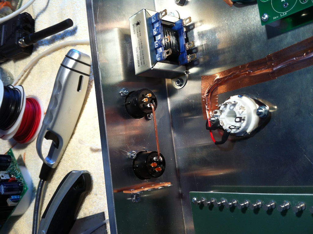
Well, it took about 6 hours but I have everything stuffed and mounted, and it passes signal.
Before mounting the transformers, I attached my signal generator right to the 1M grid resistor of the first stage, and placed a 10K resistive load on the output cap. With everything dimed, feedback loop disconnected, and a 25mVpp signal going in to the input, I get about a 100Vpp clipped output swing before the output transformer. I must have something wired incorrectly as I should have only seen about a 40V swing (or about 65dB of gain). Perhaps I wired the input transformer as a 1:20 instead of a 1:10: I'll check that first (I'm using a CMMI-10C). With the output transformer connected, I must put the interstage volume pot down near the bottom before I can hear a clear undistorted signal.
Since I used a linear taper 1M feedback pot, the gain changes drastically with a slight twist of the control, so I think I'll yank it out and put in a 12-step Lorlin instead.
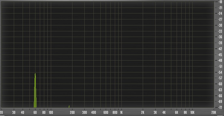
The other problem is a 120Hz hum that appears even with the volume controls all the way down. I suspect the Edcor is picking up my torroid phantom transformer as I don't see this hum on the scope if I check the signal "pre" the output transformer. I may install an unbalanced jack to confirm this.
Lastly, I hear a lot of tube "blow" noise: I'm using EH6SN7 tubes so they may need 3 or 4 days of burn in time.