Using the Pico Compressor Gain Reduction Meter with the GSSL

GroupDIY Audio Forum

Help Support GroupDIY Audio Forum:

This site may earn a commission from merchant affiliate links, including eBay, Amazon, and others.
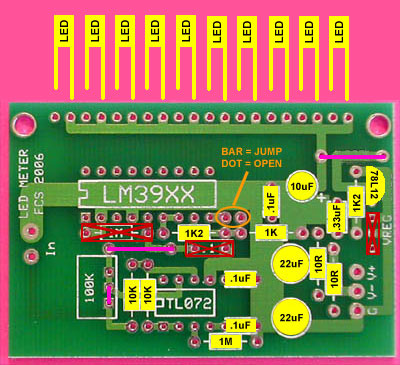
We built one with the LEDs backwards. I thought it got corrected before we took pics, but not.

I remember thinking that the bussed LED pads must be 0V when I assembled the first one... WRONG! The pads that are bussed are V+!

Hah hah!!!

Roger, no worries man! It DEF works, I'm living proof, only issue is based on that pic I stuck the LED's in the WRONG way around!!!!

I desoldered them (DS board suck for that without a desoldering iron!) and resoldered them in the rigth way, and suprise! It works like a charm.

Thanks again for the cool project, works great, and glad I could do my bit in documenting it.

Cheers

Matt
 
Hey Matta,

Could you update your pic to indicate the orientation of the LED's to absolutely avoid confusion for other builders.


Wayne,

Is there documentation on component substitutes to turn this into a standard VU type of meter? More specifically, to indicate output level on a mic preamp. I'm thinking about starting another thread on that subject, but I want to make sure that it's not covered anywhere yet...
 
Hey Matta,

Could you update your pic to indicate the orientation of the LED's to absolutely avoid confusion for other builders.

DONE! Here it is, the definitive parts overlay to use Roger's meter with the GSSL. Wayne, feel free to add it to your site.

GR_Meter_GSSL_Final.jpg


I'm removing Roger's pic to avoid confusion.

Cheers

Matt
 
Thanks Matta! :sam: :guinness: :thumb:

I'm gonna start a new thread regarding the output level meter to avoid confusion with the GSSL GR meter...
 
Roger, I'd like to buy several of your new meter boards... very cool stuff. Should I just sit tight until they show up on the website?
 
Awesome awesome awesome... when the new boards come in please contact me so I can buy a few of these. I don't want to miss this batch. Thanks.
 
PicoMeter18_Overlay.gif


My meter moves from left to right . Is this correct?
I remeber it was the other way around but for the rest it works OK.

strange..... :?
 
Actually I don't really care which way it's going, but thanks anyway.
Thing is, I soldered some caps on the opposite side of the pcb to make room for the scale switch when all of a sudden the meter went from left to right where I remember it going right to left.
I thought that maybe I had screwed something up making it go the other way around...
I guess that's not possible right? Making it go the other way around by misplacing some components....

EDIT: no, no I had the component side up AND it goes from left to right..
now I'm confused :?
 
Ok, to rule out mounting confusion...
Looking at the picture below, my meter goes from left (first led lit is the led in near the top left mounting hole) to right (last led lit is the led near the 100R resistor)

PicoMeter18_Overlay.gif
 
When compressing 20 db (full scale) I meassure - 3,2 V DC at the red dot point. Is this correct?

GSSL_Meter-_In.gif


EDIT: I guess this is not OK. This SSl sounds ok and when connecting a Sifam director meter it seems to be showing the correct amount of compression. Strange thing is that my other SSL (also with sifam director meter) meassures the same and is working fine as well...
Seems I messed up twice in the same area :?
 
Ok, Did some more meassurements. When I have +120mV on pin 3 of the audio VCA , I meassure - 2,8V at the red dot point.
This is getting confusing....
 
Hm, strange...thing is I've two proper working ssl's who meassure around -2,8V dc at the red dot point. Both work fine with the Sifam meter but obviously the led meter goes bezerk at these voltages....

They also sound good and the ratio meassures ok and all.....
 
One is using 202's gold can's and the other THAT 218o's.
Meter is a Fluke 87 DMM set to meassure DC.

Also, looking at the DBX emulation circuit I see that the red marked resistors form a voltage divider.

520qbn8.jpg


Voltage will drop at pin 3 (5534) compared to the voltage before the 1K resistor right?

When I insert a 1K sine wave (around 0,750 V AC) and turn the threshold until I get 120mV at pin 3 of the audio VCA, I meassure the following:
before the red marked 1K resistor = 1,12V DC
TL072 pin 7 = 2,3V DC
TL074 pin 8 = -2,8V DC

EDIT : forgot to mention...Make up gain is set to zero, no meter connected, both (audio) VCA's are taken out...
 
Yeah, or just put a multi turn trimmer in front....no problem I guess.

But I find it strange that I have two working ssl's (one build two years before the other) who both have -2,8V DC at the meter output where your ssl meassurs only -120mV. I'm curious what Matta's ssl meassures....
 
Thanks Roger. I'll fidel around with these resistor values until the meter works.

Still I'm very curious about how I get these high CV voltages at my meter output....

EDIT: hell yeah, comps are working fine, death quiet, on every day for at least 8 hours for 2 years already...
 

Latest posts

Back
Top