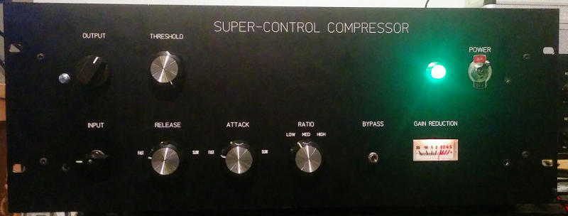
Vari mu compressor with 6V6 tubes

GroupDIY Audio Forum

Help Support GroupDIY Audio Forum:

This site may earn a commission from merchant affiliate links, including eBay, Amazon, and others.
Here's an RightMark Audio Analyzer test report http://www.kolumbus.fi/~kp5188/kompura/index.html

0 dBFS is +20 dBu but there's a 6 dB pad and and 600 ohm load resistor connected between the compressor and the sound card. Making 0 dBFS +26 dBu and the load for the compressor 600 ohms.

The frequency response is 1 dB down at 20 kHz which is good enough for me and I think good for the fairly low price of the transformers. The frequency response is -3 dB at 20 kHz to a 10k load. Distortion is also higher at 10k load. I'm going to add a 600 ohm resistor and a switch to connect the resistor to the output for the 99% of the time I'm not connecting the output to a 600 ohm load.

The noise figures aren't accurate because there's some low level hum, buzz and high frequency crap always present in my sound card.  I think the reason for that is cheaping out on my computers PSU. But there actually is some very low level 50Hz and 100Hz hum that could be done away with better layout or transformer shielding.

Here's the noise spectrum of the sound card
soundcardnoise.png


The stereo version is now complete and here's the schematic.
http://www.kolumbus.fi/~kp5188/kompura/5881stereokompura.svg

The sidechain transformer is just waste of money so I took the signal to the sidechain from the tube anode. Another way to take the signal to the sidechain would have been with a stereo pot from both anodes straight to Q3 and Q5.

With a 100k ratio pot on the sidechain high compression ratios can be achieved. I'll draw some compression curves later.

I'm using Russian Tung-Sol 5881 tubes. The tubes have been in almost daily use for 7 years in guitar amps before this and the tubes still match almost perfectly for use in this compressor. Distortion is about the same at 26 dBu output with 6V6 and 5881 tubes but in deep gain reduction 5881 has a lot less distortion. Also the frequency response is better with 5881 with the output transformers I have, -0.5 dB at 20 kHz (flat to 20kHz with 1n cap between screen grids). For this type of compressor the best way to go seems to be with 6L6 type of tubes. I'll post some distortion measurements later.

It costs less than 1000 euros to make one of these in a nice looking box and it sounds and performs probably better than most vari-mu compressors out there. I scrapped the compressor I had with the triode connected 6BA6 tubes and expensive transformers. I was never too happy with it, especially losing a lot high and low frequencies in gain reduction and high distortion.

Big thanks to PRR for the idea of using 6L6 tubes and for the sidechain design.

 
I checked out the video.  Sounds really smooth through the whole range of GR.  Nice!    :)
 
At 15dB gain reduction, at 10dBu output (600 ohm load)  THD with 1kHz signal is less than 0.5% and SMPTE IMD is less than 1%.

Here are some compression curves with input at max and threshold at min.
inputvsoutputstereo.png
 
this topic needs to be on top of the Drawing Board at all times  8)
so we all can remember this excellent project  :)

i wish i had some time to crack on with this  :(

thanks for this Heikki and PRR
 
If anybody wants to build this, other than the sidechain PCB and the low voltage power supply PCB it's best to use eyelet boards, turret boards or point-to-point construction. I'll make the sidechain PCB gerber files available for anyone who wants them. That should be enough for anyone to build their own or use the sidechain in their own designs.

The only critical part in this design is the output transformer. I used custom 25W 15k:600 transformers from Toroidy which cost around 60 EUR a piece. They need to be loaded with 300-400 ohms for good frequency response in this circuit. Plate to plate load (Rpp) of 8k seems to give the least distortion. 8k:600 transformers are available from multiple manufacturers so it's probably best to use one of those if they can handle the possibly quite large current imbalance in the primary.

In the B+ supply the only thing critical is the screen voltage. It is quite insignificant if the anode voltage is 150V, 300V or somewhere in between.

Here's the final schematic.
http://www.kolumbus.fi/~kp5188/kompura/6L6compressor.svg
The last small addition to the sidechain was to add a zener (D20) which limits the amount of maximum gain reduction. There was a problem with tubes that were less than perfectly matched. Even though the thump was inaudible or small enough to be masked by the signal. With fast attack times and large signals the sidechain could overshoot and reduce the signal nearly to zero, like in the (B) picture below. Then it would depend on the release time how long it would take to stabilize and return to the correct amount of gain reduction. Well matched tubes are still needed for best results but matching isn't as critical as before.

plop.png


etu1pieni.png
 
The frequency response is 1 dB down at 20 kHz which is good enough for me and I think good for the fairly low price of the transformers. The frequency response is -3 dB at 20 kHz to a 10k load. Distortion is also higher at 10k load. I'm going to add a 600 ohm resistor and a switch to connect the resistor to the output for the 99% of the time I'm not connecting the output to a 600 ohm load.


Did you mean -1 db at 20Hz?  If not, do you have a  figure for what you were getting on the bottom response?


8k:600 transformers are available from multiple manufacturers so it's probably best to use one of those if they can handle the possibly quite large current imbalance in the primary.

Which is another reason to see how the bass response changes along the GR curves.
 
I meant 20kHz. With the Toroidy transformers loading has a bigger effect on the high frequencies than the low frequencies. Low frequency response is -1dB at 20Hz. 

I measured the frequency response in gain reduction using white noise. At 15dB gain reduction there's some loss of low frequencies, -2.5dB at 20Hz. A lot better results than with my old 6BA6 compressor.

There is a issue with the Toroidy output transformers. If the output levels are lower than 0dBu the low frequency response starts to drop with or without gain reduction. At -20dBu it's -4dB at 50Hz. I'm not an expert on transformers but I guess the primary inductance drops at low levels. For me it's not really a problem but it might be for someone.
 
There is a issue with the Toroidy output transformers. If the output levels are lower than 0dBu the low frequency response starts to drop with or without gain reduction. At -20dBu it's -4dB at 50Hz. I'm not an expert on transformers but I

That's very interesting.  It just sounds like they require a certain drive level.  Bottom response still sounds very good for both conditions, especially considering there is no NFB.  Great work!
 
Heikki said:
At 15dB gain reduction, at 10dBu output (600 ohm load)  THD with 1kHz signal is less than 0.5% and SMPTE IMD is less than 1%.

Here are some compression curves with input at max and threshold at min.
inputvsoutputstereo.png
How did you produce these graphs? Did you post process the RMAA files?
 
abbey road d enfer said:
How did you produce these graphs?

Signal generator, Oscilloscope and LibreOffice Calc (excel). For distortion measurements I use Room EQ Wizard.
 
Heikki said:
abbey road d enfer said:
How did you produce these graphs?

Signal generator, Oscilloscope and LibreOffice Calc (excel). For distortion measurements I use Room EQ Wizard.
OK. I'm still hoping someone comes with a routine that creates superimposed graphs from individual measurements and make them look a little like they came from an AP. Dreamer...
 
I made one more using Lundahl transformers and a printed circuit board. Lundahl 1689/PP at output performs quite a bit better than the Toroidy output transformers. With Lundahl there's almost no change in frequency response at low levels or at deep gain reduction.

I used Hammond 560N for the sidechain step up transformer. Hammond datasheet for the 560N isn't accurate. Distortion is high at low frequencies even at low levels and in a test circuit I couldn't get a decent frequency response for the 600 ohm connection with a 600 ohm source. With a uncommon connection and right resistor values I made it work and got a frequency response I wanted.

http://ghr.fi/supercontrol/wiring.pdf

etupieni.png


Guts
http://www.ghr.fi/supercontrol/sisu.png


RightMark audio analyzer test report (0dBFS = +20dBu)
http://ghr.fi/supercontrol/pcbkompura2.htm

Noise figures on the test report aren't accurate because my soundcards noise overwhelms noise of the compressor.
 
Just curious, what taper is that ratio pot?

Looking at the response graph quoted a few posts above, it seems most of the ratio control is in the first ~20 percent or so of the pot. Mid position is almost all in.

If linear, perhaps an audio taper would spread it out better?

By the way, nice work and nice specs.

Gene
 
Back
Top