ok, need your opinions :'(
worked on some PCBs for this project the last week

don't want to advertise it yet, but bought an original API Lunchbox and received it a few hours ago.
(if I do this Backplane PCBs you will pay for it ;D)
first thing was to disassemble it, and it has less and some more features compared to my PCB.
now I want to know what is really needed (my PCB is configured like the standard shipping out configuration I see now)
(no manual with the API btw, loads of options but it seems you have to figure out them yourself)
the Lunchbox has (what my PCB doesn't have):
- output load footprints (no resistor fitted)
- +4/-2 output solderbridges (PCB traces to +4, for -2 you would have to cut and solder)
- +4/-2 input solderbridges (PCB traces to +4, for -2 you would have to cut and solder)
- footprints for the gain resistor (no resistor fitted)
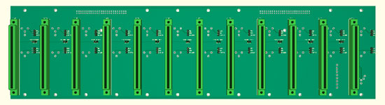
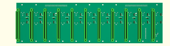
my PCBs have some other options right now (which the Lunchbox doesn't have):
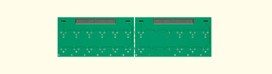
- main backplane with 11 slots (12 to follow)
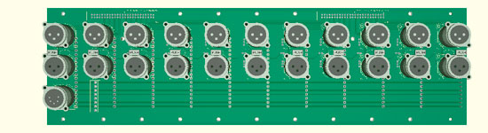
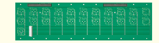
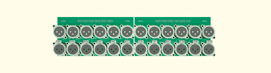
- XLRs mounted at the backplane or via two 50pin SCSI ribbon cable connector to a remote XLR backplanes
(remote XLR panels for a deeper case to include an internal PSU)
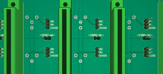
- each XLR on the backplane can be jumpered either to GND or chassis
- the remote XLR PCB can be jumpered to connect all input XLRs to either GND or chassis, also all output XLRs
which of the original API Lunchbox features are really essential ???