11 Slot DIY API 500 series rack

GroupDIY Audio Forum

Help Support GroupDIY Audio Forum:

This site may earn a commission from merchant affiliate links, including eBay, Amazon, and others.
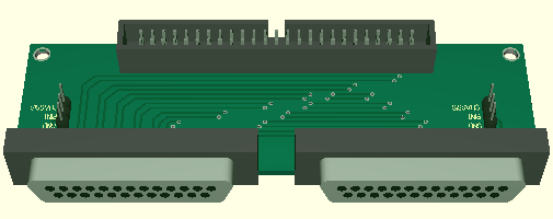
if you've already got the dual row headers for a ribbon cable containing all the outputs (to do a "remote" output) on your backplane, then i recommend creating an optional db25 pcb, that connects to that ribbon header and brings those out to the three db25 connectors.  the chassis can be punched for the three db25s as "knockouts" where the user can bend them off if needed and install the db25 pcb - the db25 connectors themselves can secure the pcb to the chassis backpanel; perhaps also a few holes for standoffs can be provided.  another method would be to supply the db25 pcb with a pdf drill template so that users who want that option can install it themselves, using someone local with a db25 punch.

not sure if the pinout you chose is already designed for this, but some SCSI standard cables are wired differential, with each pair twisted, which would be good for balanced audio.

as a commercial product i would say the 18pin edac option is a mistake, but it sounds like a DIYer's dream come true.

nicely done volker.

ed
 
The module width is 38.1mm as standard. Hence the pitch between the module centers is also 38.1mm

EDAC centre is 11.12mm to the left from the module center.

Just a note on 12 slot; this is done with the idea that it can be used to construct a modular console. Otherwise it is non standard.


Cemal
 
edanderson said:
... creating an optional db25 pcb, that connects to that ribbon header and brings those out to the three db25 connectors ...
I will look into this. wouldn't four connectors be better to have separated ins and outs ?
 
sahib said:
The module width is 38.1mm as standard. Hence the pitch between the module centers is also 38.1mm

EDAC centre is 11.12mm to the left from the module center.

Just a note on 12 slot; this is done with the idea that it can be used to construct a modular console. Otherwise it is non standard.

Thanks Cemal, that was a dumb question  - realised after I woke up on the way to work! Standard module width obviously. Great work you guys.

Cheers Tom
 
[silent:arts] said:
edanderson said:
... creating an optional db25 pcb, that connects to that ribbon header and brings those out to the three db25 connectors ...
I will look into this. wouldn't four connectors be better to have separated ins and outs ?

yes, sorry that was a slip on my part.  you'd want four db25s, two for in (eight slots on one, two on the other) and two for out.  arguably you could just do two since one db25 will only have two channels on it.  you definitely want to use the tascam db25 pinout, so that people can buy pre-fab cable harnesses.

http://www.whirlwindusa.com/ftp/Connectors/db25/wwdb25tascpin.pdf

ed
 
each of the SCSI connectors has 6 ins and outs
easiest would be (like with the XLR PCBs) doing one PCB for each SCSI connector
which means 6 inputs and 6 outputs each SubD (Tascam pinout for sure)
would save some PCB costs (and some headache with routing the PCBs ...)

is this an option you could live with ?
 
Looks really nice Volker!! Would be nice to see the DB25 options, but it's not critical for me. Thanks for doing all this!!
 
I'll take 10 of the 12 slot boards w/db25 adaptors

and again Very Nice Work!!!

Wilebee
 
wilebee said:
Perhaps the next boards can be channel strip motherboards? :eek:
what is a channel strip motherboard ?
and, since you want ten 12 slots with SubD25:
6 in / outs on each is alright ?
leaving out channels 7 & 8 at the Tascam layout ?

btw, can anybody tell me why the channel assignment from Tascam is inverse for PCB use ???
(looking at the back of a SubD female channel one is at the right side, channel eight on the left)
 
Very sweet!  I'm happy this is becoming a reality!  I don't have any 500 series stuff because the initial price of a lunchbox is just too expensive.
 
b3groover said:
... because the initial price of a lunchbox is just too expensive
bought one for christmas :)
might be the exchange rates we have at the moment (paid EUR 400,- incl. shipping, brand new with warranty from a dealer in the UK)
build quality is good, PSU looks ok, and the backplane PCB is thicker than 3mm
not too bad :)
 
SubD I/O (six channels inpout on one, six chanels output on the other SubD25 - Tascam pinout)
use two PCBs for 11 or 12 slots

512SubD.png


silent:arts, based on the work you've done on this project, I think this should be your new avatar:

mrincredible.jpg


---Joe


[silent:arts] said:
SubD I/O (six channels inpout on one, six chanels output on the other SubD25 - Tascam pinout)
use two PCBs for 11 or 12 slots

512SubD.png
 
Back
Top