kante1603
Well-known member
Yes.irfrench said:Enjoy?


Yes.irfrench said:Enjoy?
irfrench said:...
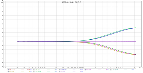
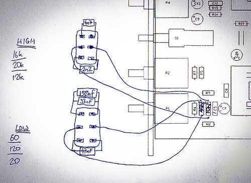
This includes the switch-able additional LF and HF shelf frequencies with lowest/middle/highest freq. select for the mid-band section.
Enjoy? ;D
At least it explains why I heard the HF shelf differences as being quite subtle!
Ian,
8)
")
irfrench said:At least it explains why I heard the HF shelf differences as being quite subtle!
irfrench said:Me again
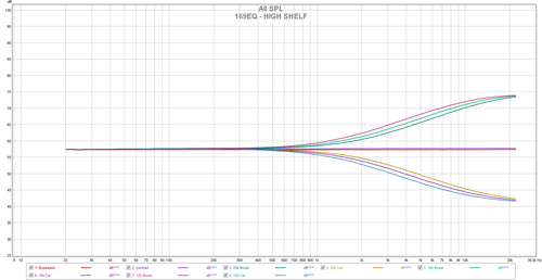
Just a quick note to say I made the changes (above?) and the EQ curves became:
A bit more separation and the differences now are definitely less subtle!
I also wanted to do a comparison (for my own curiosity) between the IC and DOA options - so I ran a short recorded acoustic passage out to the same EQ, once with IC's once with DOA's. I hope it is of interest:
https://soundcloud.com/minoian/sets/oa10-comparison
Thanks,
Ian

ignoring level mismatch by missing/not shown bypassing of the HPF, probably yes.dirtyhanfri said:I´m thinking in adding a HPF on this EQ, would it work inserting it before C3 (after the first IC)?
Drop the gain of the balanced line receiver by 3dB to compensate for the HPF filter boost (maybe solder 23K71 resistors in parallel to the 10Ks R3 and R4 for ideal close matched value 7K071s). Sourcing dual rev.log 47K pots might be the hardest part. A dual pole switch for one or more HPF freq. might be easier to source. Don't leave the other half of the TL072 unconnected. Maybe have a look at the Barry Porter NetEQ HPF section for a similar/bypassable approach.My only reason to use this is because it´s the easier I´ve found right now, I don´t need nothing fancy, just filter some low freqs. Also, I think the TL072 will drive finely the eq or I´m wrong?
As suggested and not shown on your pic. If you make the full CCW setting of your switched HPF low enough, this might operate like a bypass.dirtyhanfri said:The idea is using a Lorlin 2 way 6 positions switch for the freq selection.
To bypass it I was thinking in a simple dpdt.
Place a -3dB voltage divider in front and use the TL072 2nd.half to buffer this attenuator if you want to implement a bypass switch. With HPF always in circuit, dropping the gain of the balanced line receiver as previously described seems the easier solution. (as previously mentioned, have a look at the NetEQ).For the other half of the TL072, what do you suggest? route to ground the three pins?
Your pic shows an equal value sallen-key filter. This type has gain in the pass band. Sallen-key filters with unity gain in the pass band will not have equal values for the frequency setting C and R parts values.And the level mistmatching you mention, would be gone with the hpf bypassed? (Sorry, but I'm still learning a lot of concepts) So, there's a boost in the schematic attached? Maybe messing with the value of the resistor between pins 1 & 2 of the IC will solve it?
Enter your email address to join:

