Yamaha PM700 console upgrade/mod

GroupDIY Audio Forum

Help Support GroupDIY Audio Forum:

This site may earn a commission from merchant affiliate links, including eBay, Amazon, and others.

spaceludwig

Well-known member
Joined
Jul 14, 2011
Messages
186
P6163200.JPG


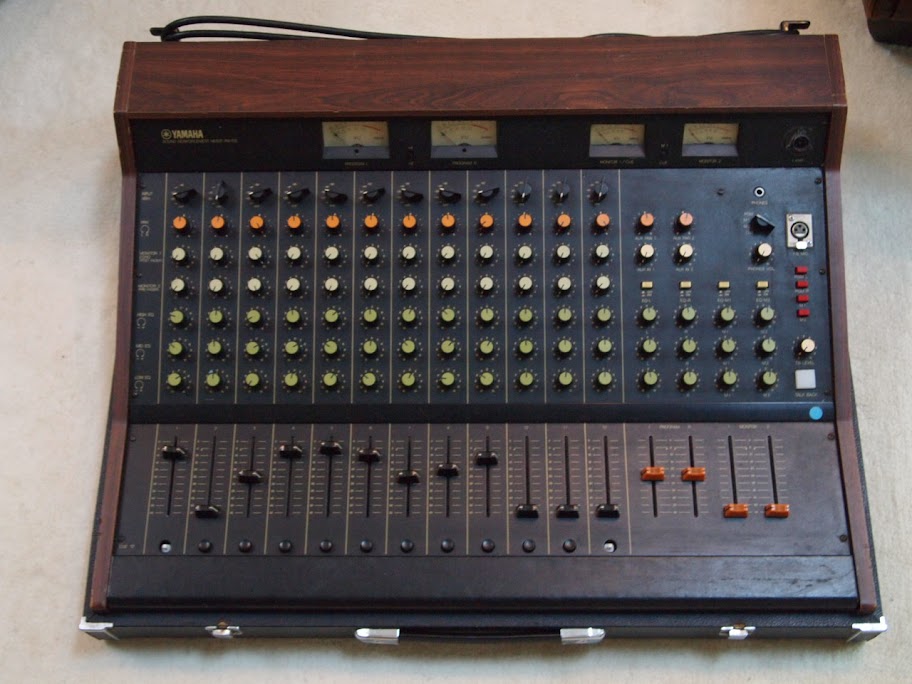
I'm overhauling this old console I bought almost 10 years ago that I never got around to completing. In an effort to encourage advice/discussion/words-of-wisdom, and simply to make a record of the steps taken that someone else might find useful in the future, I've decided to start this thread. This is nowhere as sexy as most of the hi-end gear being worked on, and salivated over,  by other members on the forum but I've heard this console has its merits and I can't imagine why I would get a summing box if I have this on hand. My feeling is some of its shortcomings might be a good complement to the clinical precision of digital audio. 

I have a number of ideas of what I would like to change/modify but I will try to keep my goals simple and disciplined (too many scattered ideas = too much time searching & gathering info = nothing ends up getting done). 

As per my other post, I have already changed the first opamp right after the transformer on each input channel and made a new ribbon cable to connect the channels together as the original was faulty all over the place. 

My immediate goal is to recap every channel. They are:

LC80883 Input Channel x 12

LC80883%20Input%20channel-1073.jpg


LC80903 Program (L & R) x 2

LC80903%20Program%20%28L%20%26%20R%29-1077.jpg


LC80193 Monitor 1

LC80913%20Monitor%201-1074.jpg


LC80924 Monitor 2 (headphone)

LC80924%20Monitor%202%20%28headphone%29%20-1076.jpg


LC80933 Talkback

LC80933%20Talkback-1075.jpg


To remove the original caps on the 12 input channel strips I found it quite helpful to make a simple template of what needed to be desoldered by using a red dry-erase marker to make dots on the PCB

PCB%20Reference%20dots-1078.jpg


which I could then refer to.  This made the process a lot less tedious.

As of this writing I am waiting for my order of replacement caps to arrive. Which brings me to the next step and my first question.

I replaced IC 1 in the schematic below

Input%20Schem%202.jpg


I thought the two other opamps in the circuit were to send the signal to the monitors but it would seem from the schematic above that the audio signal passes through IC 2 also. Is this correct?


Yes, I'm pretty sure IC2 is providing gain after the fader and providing a low impedance for the pan potentiometers (Dual pot)

I'm not sure I can decode the rest with much certainty. I have some Yamaha 916 channels which I have studied and there are similarities...
 
I will try re-sizing the pictures. When I previewed my post I could see them in their entirety but now they seem cut off.
 
Another question: since I am using this as a summing mixer, can I replace the current 600:3k microphone input transformers for 1K:3K line input transformers? The input channels will be connected to the line outputs of my sound card.
 
Between pins 1 and 6 of each IC there is a 10 or 22pf cap and a 47pf cap from pin 1 to ground.

Question:  Can I remove these if I am not using the stock chips and if the opamp I am replacing them with does not require a freq comp cap (i.e. NE 5534)?


Following are some pictures of the 14 extra adapters I had to make to replace the original IC's on the input channel boards. These are probably only of interest to those that want to undertake similar mods for this board but have no reference to guide them. My own efforts my be subpar so feel free to comment if I am committing some errors.

To begin with you'll need a virgin PCB project board

PCB%20board-1080.JPG


After drawing some guidelines it is advised you secure it well before cutting

PCB%20clamped-2.JPG


Next, break out the chainsaw. My tool of choice was a dremel I bought for under $10

PCB%20dremel-2.JPG


Cut them so that they are 7 pins wide, like the original IC. Pins 2 and 3 should be severed as these need to be swapped since the original Toshiba IC's don't have the same pinout connection as contemporary chips.

Adapter-1090.JPG


Next you'll need some sockets to comfortably interface your adapters to the channel boards

mounts-1093.JPG


Pins 2 & 3 need to be swapped. You need to make some jumpers between pins 6 & 7 to their respective sockets. A finished adapter

Adapter%20in%20aligator%20clip-2.JPG


The miserable lot that took a good part of my day

Adapters%202-1143.JPG
 
When replacing IC number 3 on the board with the adapters I made I run into what might be a problem. Namely, the rear of the adapter touches some capacitors that are directly behind it. Below are 2 pictures to illustrate what I mean

Adapter%20right%20side%20close%20up%202-1146.JPG


Adapter%20right%20side%20close%20up-1150.JPG


Is this okay? Can stray capacitance - or any other phenomena - impact the signal negatively? Is it better if I place the adapter on the solder side of the board like this?

Adapter%20solder%20side%20-1153.JPG


Please advise as I am not comfortable with the close proximity to the other components, but I might be worrying for nothing. 
 
You could move the ceramic disk capacitors to the other side of the board instead. This is quite common even on some mixer channel strips straight out of the factory. I suspect there won't be problems with stray capacitance with anything related to the adapters. All connection distances seem very short.

By the way, nice job making the adapters. Brown dog adapters would have been far more expensive, like $3 each if I remember correctly.
 
Kingston said:
You could move the ceramic disk capacitors to the other side of the board instead. This is quite common even on some mixer channel strips straight out of the factory. I suspect there won't be problems with stray capacitance with anything related to the adapters. All connection distances seem very short.

By the way, nice job making the adapters. Brown dog adapters would have been far more expensive, like $3 each if I remember correctly.

Lol, what a simple solution and yet it never occurred to me. That's what I'll do.

As for brown dog they don't make a dip to 7 pin.
 
Thanks. I received my caps from mouser. They are the nichicon muse series. I look forward to hearing the updates vs. original.

BTW, abechap, did you keep the original yamaha DOA when you racked your channels? Or did you change them for something else?
 
3nity said:
what are you trying to use as op-amp??
thanks.

Either the opa604 or 227. I'll compare them to the stock opamps on the channels. I'd be happy to record my findingss and post them if someone could recommend 1 or 2 musical pieces or songs suitable for such a comparison.
 
spaceludwig said:
BTW, abechap, did you keep the original yamaha DOA when you racked your channels? Or did you change them for something else?

The original DOAs sound surperb IMO. They are the reason I got those channels in the first place!
 
Hello again, been a while. I had an incident that resulted in a broken nose, fractures and other displeasures so I had no desire to solder and have lead fumes wafting through my swollen face and contaminating my wounds, not to mention compounding my insanity....

That said, I finally finished recapping all modules and swapping out two of the three original IC opamps in the signal path for the adapters I made above.  Below is a picture of some completed modules:

Several%20units%20finished-1302.jpg


A close up of the adapters facing each other on the board:

Adapters%20on%20PCB-1319.jpg


To make this easier I followed Kingston's advice (above) and placed the ceramic caps around IC3 on the BCB side of the board:

Caps%20on%20PCB%20side-1321.jpg


The green caps are bipolar. Here's a tin full of my decapitated victims:

de-capitated-1305%2002.jpg


For the sake of reference below are pictures of the power supply and main meter PCB:

Power%20supply-1304.jpg


PRGM%20meter%20board%20top-1308.jpg


PRGM%20meter%20board%20bottom-1309.jpg


The meter circuit has been recapped also.

I will now re-assemble the unit and make sure every channel is working. I also bought a lot of 14 Tamura GA80071 transformers
PM2000%20line-in%20transformer%20block-1313.jpg

with which I would like to replace the original GA8027 input transformers. I have some questions but will start a new thread as I suspect some people will avoid this one due to the gear being worked on.

I will post more updates as I have them. Again I welcome and all comments/advice/critiques.

Cheers!
 
not going to argue with you wanting to replace the original transformers....but all I can tell you is in my mic preamp that uses those transformers and those same discrete opamps found in your console, sounds really good.

Especially with a thing like transformers, buying that many to upgrade might double or triple the cost your putting in but maybe only "upgrade the sound" 1%, 2% percent (and that would be subjective because these transformers have a really cool slight coloration!)
 
Hmm, I've read that the GA80071 retains more of the bandwidth while offering some color. Of course, I haven't heard this for myself so just jumped at what I thought was a bargain when I saw one. Perhaps I'll just change a couple and see what the difference is. At worst I can always resell them on the black market, though I'd definitely want to hear the difference first.
 
OH!!
HAHA Wait a minute!!

Back up, I got ahead of myself. I was skimming your post and saw the picture and read "I want ot replace the original input transformers"

Duh sorry. You are replacing them WITH the ones in the pictures. Yea the GA80071 are the ones I used. They sound good. I remember now that the PM700 uses crappy looking little transformers on each channel. Good on ya for upgrading!!

Tho like anything....they are always useful on something. Part of the fun of modding is customizing. leaving a few channels with stock transformers like you were saying. Atleast for a while to get a feel for if they saturate in a pleasing way. (might be the ticket for guitars and drums!)
?IDK!

 
That's a relief!

BTW, since you are using the GA80071 could you please tell me which wires are the primary and which the secondary? I did a search all over the board and the info is scant and nothing is definitive. With so many racked PM1000 & PM2000 units someone's got to have this info. Perhaps you can just snap a quick picture and post it?

 
Ah yes.

If you have a mystery transformer, you can measure the DC resistance of the different wires until you have something that makes sense.

I think these ar 1:3 ? ish step up transformers. SO one side is going to read low ohms (should have a center tap wire brown I believe, thats where your phantom power goes if you want, but you still need to use a resistor i forget what size) and the other-side should read higher DC resistance (1k ish) that goes to your circuit.

Polarity....well thats a good question. If you have a scope great, otherwise your going to actually hook up a channel and test it against a pre you know to be wired correctly. Unless someone recollects off hand....cause I don't...But i'm getting some pm1000 channels here soon, I'll be able to tell you exactly how they are wired up
 

Latest posts

Back
Top