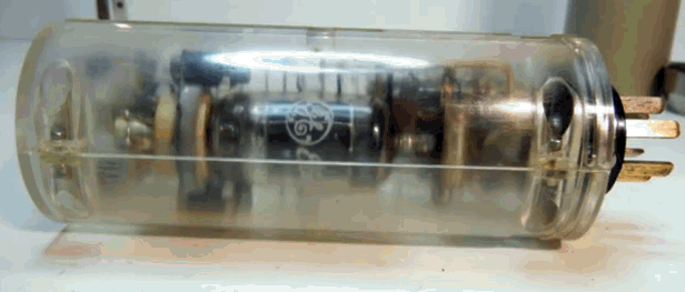
Telefunken ELA M 251 Clone Tube Microphone Build Thread (D-Ela M 251E)

GroupDIY Audio Forum

Help Support GroupDIY Audio Forum:

This site may earn a commission from merchant affiliate links, including eBay, Amazon, and others.

poctop

Well-known member
White Market Member
Joined
Jul 15, 2009
Messages
2,306
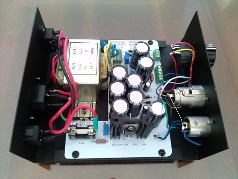
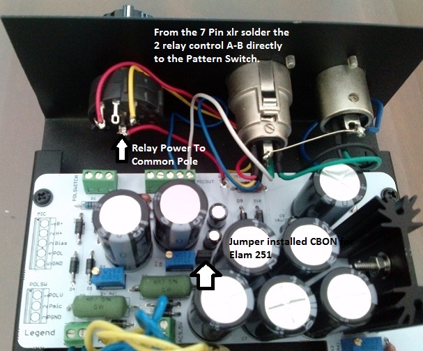
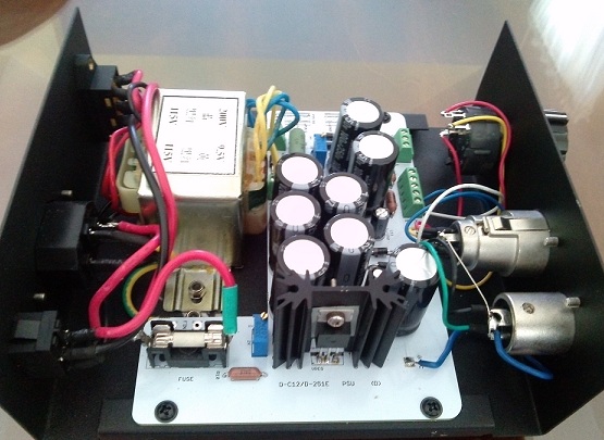
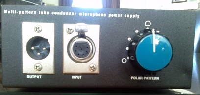
D-Elam 251E with True Pattern Switching on PSU ,  

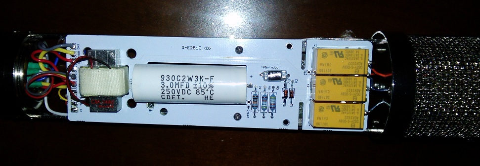
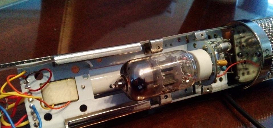
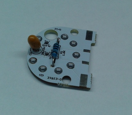
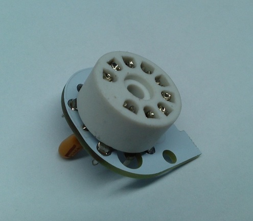
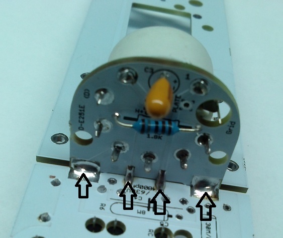
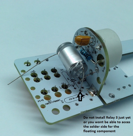
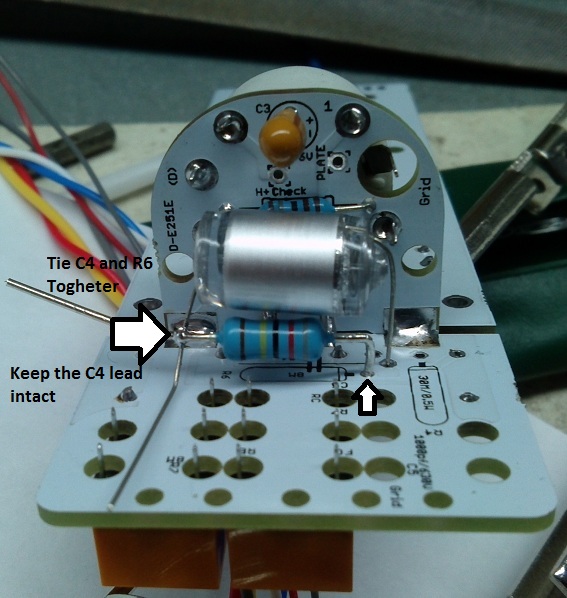
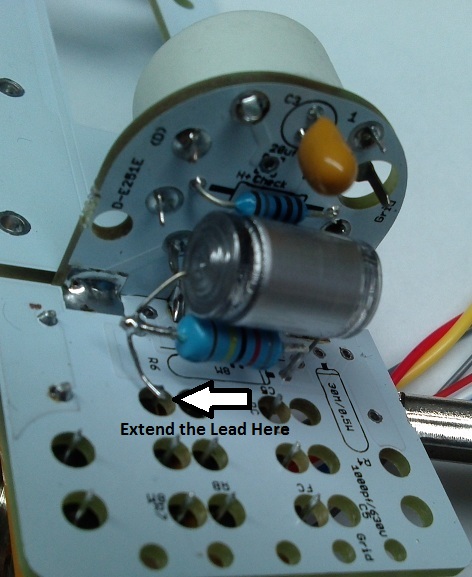
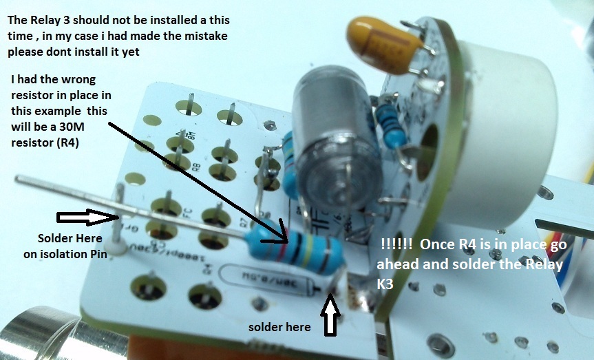
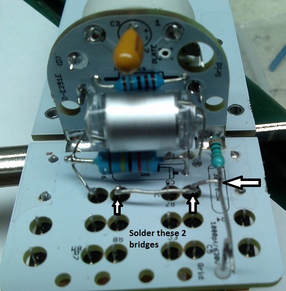
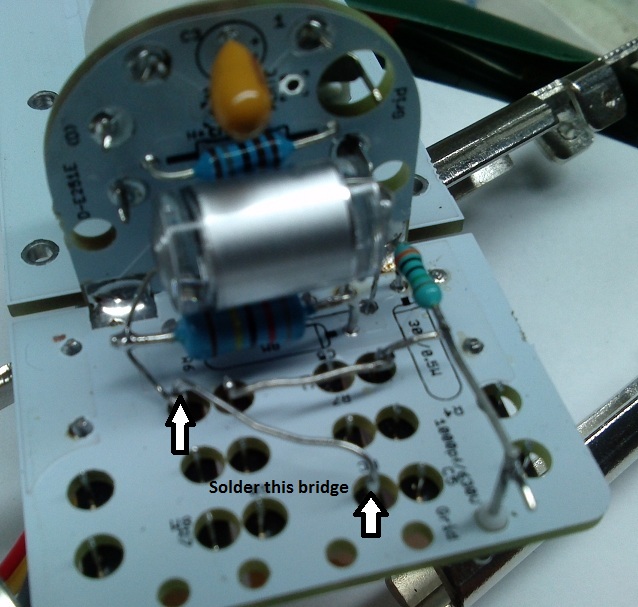
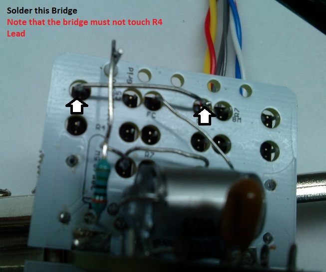
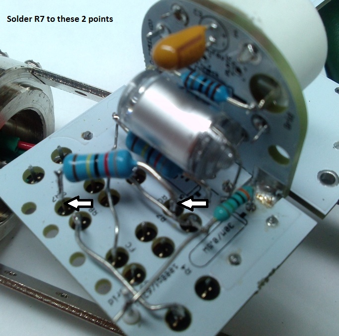
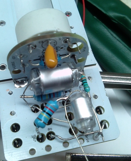
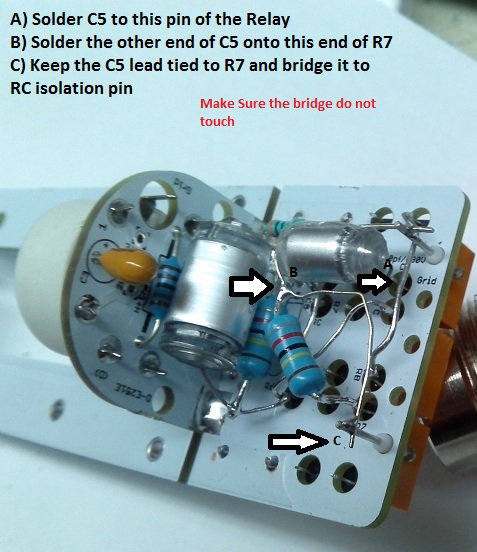
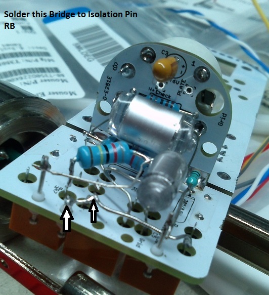
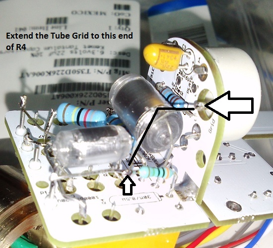
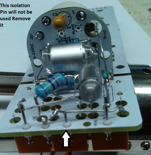
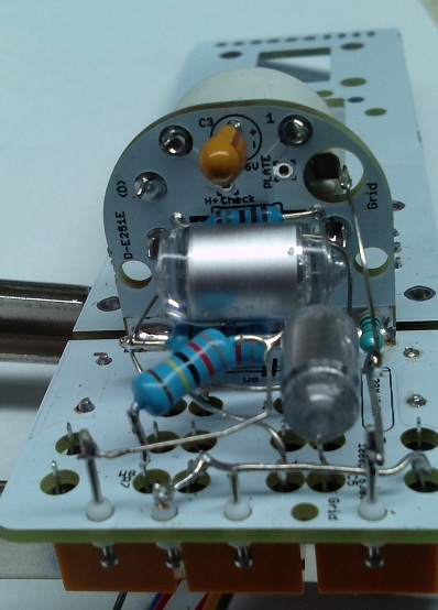
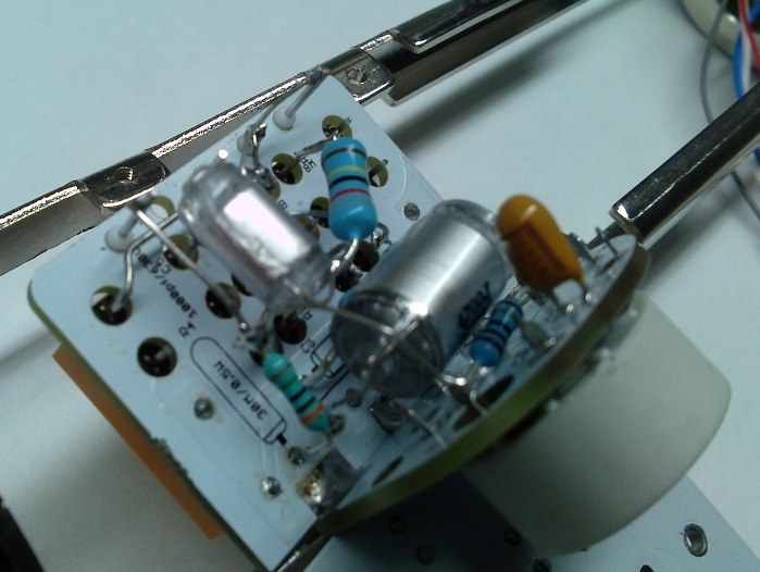
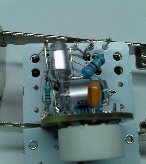
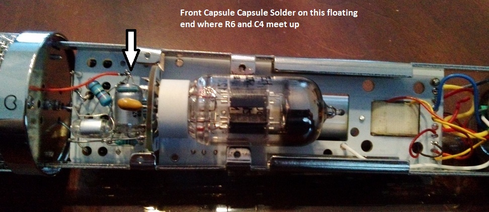
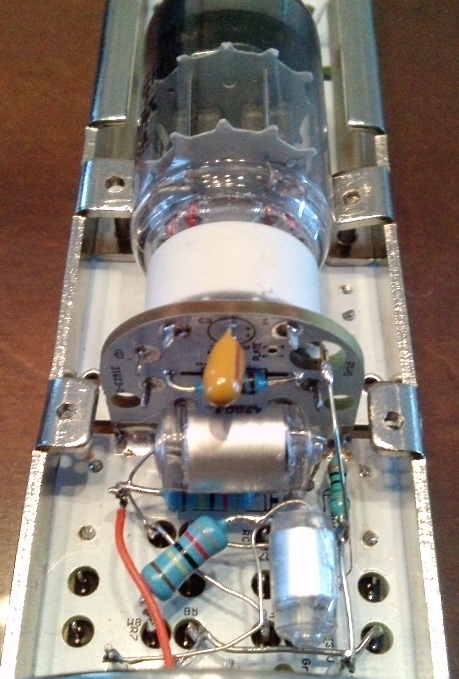
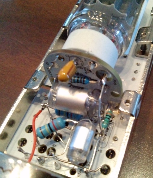
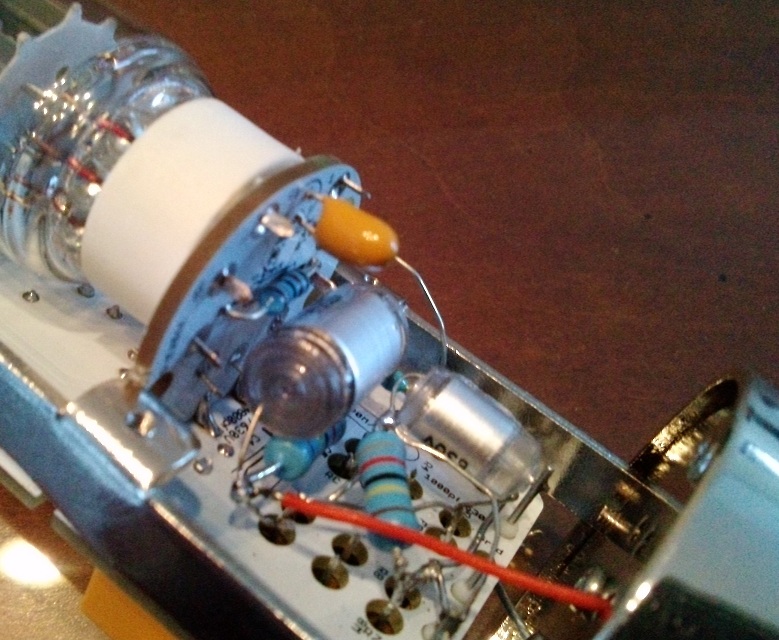
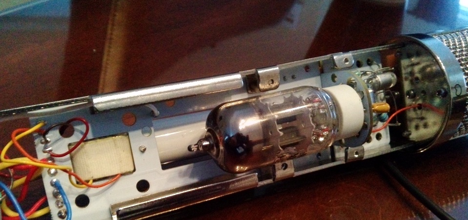
this was a very fun build.  Specially the Point to Point HZ bridge,  half PCb/half PTP for Optimal Results and Maximum Fun

Enjoy,
more Info soon at http://www.vintagemicrophonepcbkit.com Or http://groupdiy.com/index.php?topic=49675.0

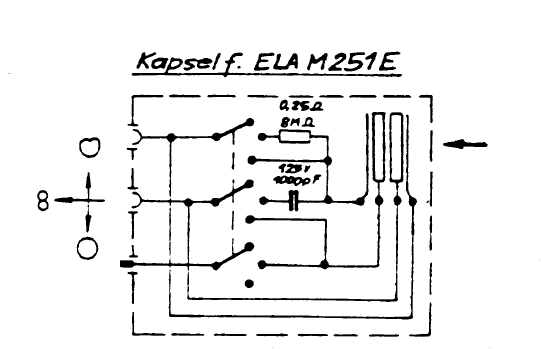
Schematic ELA M251E
https://cdn.groupbuilder.com/groupdiy/u/39511/58d1402a06402.pdf

Schematic D-E251E
https://cdn.groupbuilder.com/groupdiy/u/39511/58d1402a0643e.pdf

PsU
https://cdn.groupbuilder.com/groupdiy/u/39511/58d1402a06450.pdf

thanks to Trans4funks1 for this nice work.  :)

Microphone DiaGram
https://cdn.groupbuilder.com/groupdiy/u/39511/58d1402a06461.pdf

PSU DiaGram
https://cdn.groupbuilder.com/groupdiy/u/39511/58d1402a06473.pdf

PSU BOM Only
http://www.mouser.com/ProjectManager/ProjectDetail.aspx?AccessID=721fb79f74


Elam 251 BOM. (Missing From BOM 4700pf Polystyrene 630V and 1000pf Polystyrene /630V and 100pf Polystyrene 630V)
http://www.mouser.com/ProjectManager/ProjectDetail.aspx?AccessID=d2c3022a97

List Of interesting Tweaks From User and Group Member
I compile them as I go ,

Ok , here is some tweaks you can do from original schemtics,

SuggestedTweaks

100uF or more  on the cathode bypass cap instead of 22uF (C3) bass response
increase the output LP filter by increasing the 120pF to 220pF or even 330pF ... (or more to taste)  (C2) bass response
Grid to ground resistor higher  100m or 250m (R4) Bass Response
Increase or decrease output coupling cap to taste to modify low end response  (C1) to taste


58d1402a06486.jpg


58d1402a06496.jpg


58d1402a064a7.jpg


58d1402a0283f.jpg


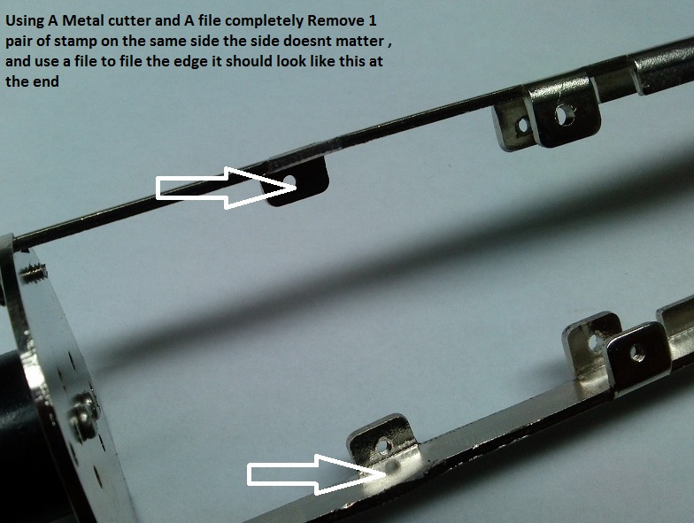
It is needed to get rid of a pair of  high stamping Metal siders to proper with the aid of a metal cutter and a file  :p
58d1402a064c9.jpg


58d1402a064da.jpg


58d1402a064e8.jpg


58d1402a064f9.jpg


58d1402a06506.jpg


58d1402a06518.jpg


58d1402a06529.jpg


58d1402a0653b.jpg


58d1402a0654d.jpg


58d1402a0655a.jpg


58d1402a0656b.jpg


58d1402a06579.jpg


58d1402a0658a.jpg


58d1402a0659c.jpg


58d1402a065ad.jpg


58d1402a065bf.jpg


58d1402a065d0.jpg


58d1402a065e2.jpg


58d1402a065f3.jpg


58d1402a06621.jpg


58d1402a06633.jpg


58d1402a06644.jpg


58d1402a0665a.jpg


58d1402a0666d.jpg


58d1402a0667b.jpg


58d1402a0668c.jpg


58d1402a0669e.jpg


58d1402a066af.jpg


58d1402a066c3.jpg


58d1402a066d4.jpg


58d1402a066e6.jpg


58d1402a066f3.jpg


58d1402a06706.jpg


58d1402a06718.jpg


58d0281993f9b.jpg


Best,  :)
DAN,
 
Yay! What tranny is that? Will the BOM include electrolytic, wet tantalum, etc. like the original?

Why does your headbasket have a cardioid symbol? That's not right haha
 
RuudNL said:
Is the schematic available?
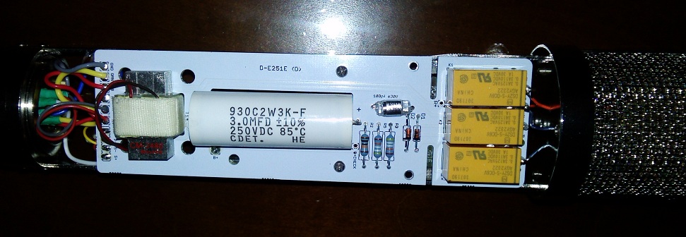
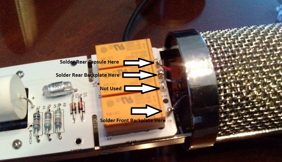
What is the function of the relays in this version?
(As far as I know there was no relay in the original ELA M 251)

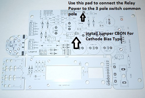
The Relay are used To control this scheme, its all Floating Ptp for the realy control as this control the capsue.

58d0281993faa.jpg


Best,
Dan,
 
RuudNL said:
Is the schematic available?
What is the function of the relays in this version?
(As far as I know there was no relay in the original ELA M 251)

the polarisation switching is done via remote controlled relays. I did te same in my mic, but all point to point, looks a bit wild but works fantastic.

you have to get relays with good isolation resistance.

in the original it's a switch
 
Melodeath00 said:
Yay! What tranny is that? Will the BOM include electrolytic, wet tantalum, etc. like the original?

Why does your headbasket have a cardioid symbol? That's not right haha

The Transfo is a Cinemag 2480 for now , I do have BOM available ,
Best,
dAN,
 
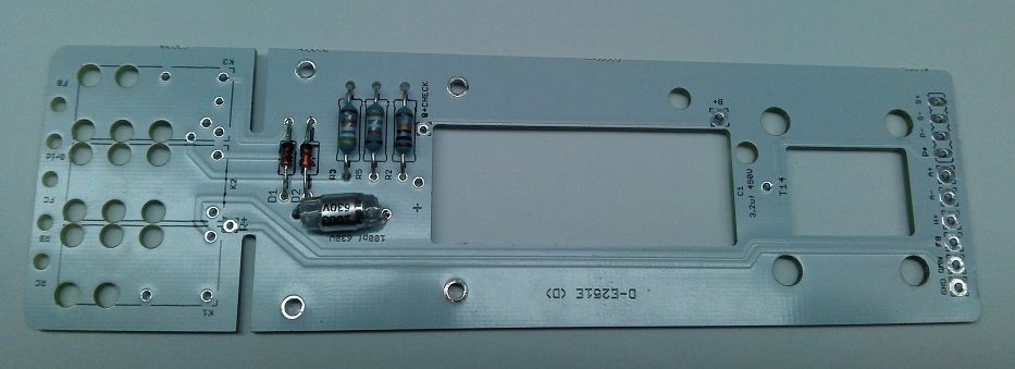
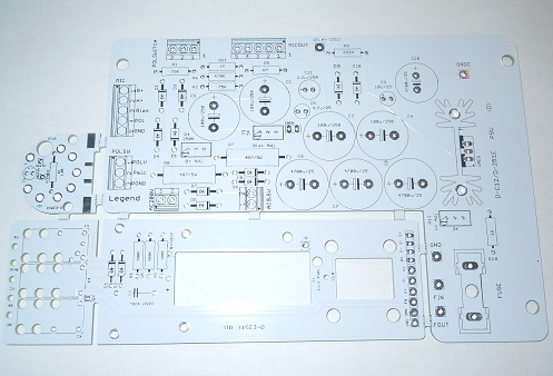
It almost seems like the board is a piece of garolite with a printed sheet attached to it.  What is it?

I would like to build a 251 for my fist mic mod and I have been looking at switches etc.

Can you explain more about how to use the relays, or do you perhaps plan to release a PCB kit and a schematic of this particular build?

I'm excited to see what you have done! :)
 
trans4funks1 said:
It almost seems like the board is a piece of garolite with a printed sheet attached to it.  What is it?

I would like to build a 251 for my fist mic mod and I have been looking at switches etc.

Can you explain more about how to use the relays, or do you perhaps plan to release a PCB kit and a schematic of this particular build?

I'm excited to see what you have done! :)

the 3 relays are used to Operate all the pattern like the original elam would, but it can be done on the psu as this kind of switch is nearly impossible to find ,
Works awesome ,
Best,
dAN,
 
It almost seems like the board is a piece of garolite with a printed sheet attached to it.  What is it?

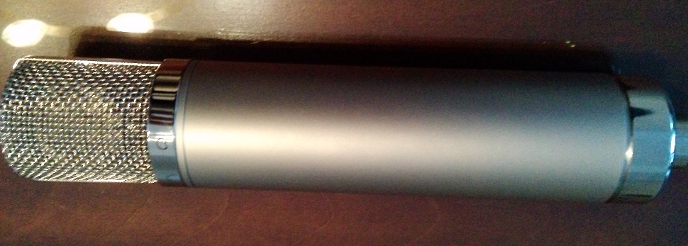
FR4 PCB,  I Actually Call this mic , the Walter White,  ;D

Best,
Dan,
 
I do have 6 kit left for those who would like to jump in  :eek: ,

PM me if interested,

Best,
DAN,
 
I'm very interested in viewing a schematic of how the relays are specifically implemented in this circuit.

I was reading the data sheet for them and I am having difficulty imagining how the various pin outs on the relay fit into the traditional circuit.

I have attached a screen shot of what I think is the part of the data sheet that applies. I have a self made drawing of the 251-E circuit that is essentially a copy of the official AKG version posted in the OP and I would like to, as an exercise in learning, incorporate the relays in a new schematic so that I can fully understand what is going on.


Attachments

  • Relay-detail.gif
    Relay-detail.gif
    24.9 KB
Hi DAn et al,

I'll be building this bad boy with BeesNeez bodies and no donor PS etc.

Could someone please point me in the direction of an appropriate trafo 240 primary, dual secondaries? Have googlised it with minimal success.

Or do I need 2 separate trafos? How much power for each?

Thanks for your help.

Matt
 
Woot said:
Hi DAn et al,

I'll be building this bad boy with BeesNeez bodies and no donor PS etc.

Could someone please point me in the direction of an appropriate trafo 240 primary, dual secondaries? Have googlised it with minimal success.

Or do I need 2 separate trafos? How much power for each?

Thanks for your help.

Matt

I think the simplest and most efective way is try to get a HT-11 PSU unit from Chunger ,  you will be done in a hour

Yes you would need a 9.5V ish tap and a 200V tap,
Best,
Dan,

 
Yeah, Im  a bit reluctant to buy the whole kit when the only bit I'll need is the trafo essentially. I want to do these with Galaxy cases and other bits and pieces that I already have.

Also, can you recommend a place to source the 7 pin XLR inserts with retaining grub screw?

Thanks again,

Matt
 
Hi Dan, in the original schematic, was the 3.2uF output cap an electrolytic or perhaps wet tantalum? I haven't been able to find anything definitive. I found a wet tantalum but it's value is a little high, and voltage is only 125V. It's also expensive!
 
Looks like a wet tantalum to me , but they may have had different type over times ,  as Metal paper, polyester also,
Why Not polyprop
Here is a shot ,.

http://www.youtube.com/watch?v=rJx9TdJSFRI

58d0281993fdb.gif

Best,
Dan,

your guess now,


Woot said:
Yeah, Im  a bit reluctant to buy the whole kit when the only bit I'll need is the trafo essentially. I want to do these with Galaxy cases and other bits and pieces that I already have.

Also, can you recommend a place to source the 7 pin XLR inserts with retaining grub screw?

Thanks again,

Matt

Just Ask Chunger he should be able to provide those items for you ,
Best,
Dan,

 
Back
Top