You are using an out of date browser. It may not display this or other websites correctly.
You should upgrade or use an alternative browser.
You should upgrade or use an alternative browser.
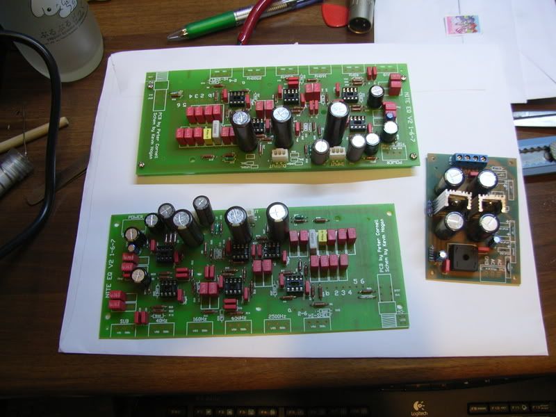
3D "AIR" EQ - "Night EQ" PCB's Complete!
- Thread starter khstudio
- Start date


Help Support GroupDIY Audio Forum:
This site may earn a commission from merchant affiliate
links, including eBay, Amazon, and others.
khstudio
Well-known member
Looks good but damn those caps are BIG :shock: .
:green:
:green:
funkdrmr
Well-known member
I found a small store here on Oahu that has nearly everything I need for this project! They even have the resistors / caps separated and labeled, but not by brand name.
The 470uf/63v caps I found there are CONSIDERABLY shorter than what you have on your boards. I can't tell what brand they are, though.
Is there any color scheme for the caps that I can use to tell what brand they are? Maybe abreviations of the company name on the caps themselves?
The 470uf/63v caps I found there are CONSIDERABLY shorter than what you have on your boards. I can't tell what brand they are, though.
Is there any color scheme for the caps that I can use to tell what brand they are? Maybe abreviations of the company name on the caps themselves?
funkdrmr
Well-known member
Sorry for the noob question here, everyone, but I've GOTTA ask.
I just got done stuffing all of the resistors, but noticed something I'm unsure about.
On the PCB there are some 22R resistor spots labeled RPSU.
I'm assuming 22ohm resistors go there....also, could someone tell me what RPSU stands for, or what these do in the circuit?
Thanks and Happy New Year!
I just got done stuffing all of the resistors, but noticed something I'm unsure about.
On the PCB there are some 22R resistor spots labeled RPSU.
I'm assuming 22ohm resistors go there....also, could someone tell me what RPSU stands for, or what these do in the circuit?
Thanks and Happy New Year!
peterc
Well-known member
I use RPSU to indicate a resistor from a power rail to the supply pin (usually on an opamp). It isolates the opamp from the supply line, in conjunction with a cap, usually labelled CPSU
They are usually 22R or so in value.
Peter
They are usually 22R or so in value.
Peter


![Soldering Iron Kit, 120W LED Digital Advanced Solder Iron Soldering Gun kit, 110V Welding Tools, Smart Temperature Control [356℉-932℉], Extra 5pcs Tips, Auto Sleep, Temp Calibration, Orange](https://m.media-amazon.com/images/I/51sFKu9SdeL._SL500_.jpg)


dagoose
Well-known member
My Nite EQ is up and running! well... i tested it and it works great! Now i need to order my frontpanel at schaeffer and it can be racked up ")
It sounds really sweet, i love the air section on 40khz, it freshens up the sound without getting harsh. Just did some quick tests but so far i'm really happy with the result, no hum, noise or what ever, just sweet EQ'ing.
Here is what mine looks like from the inside right now.

It sounds really sweet, i love the air section on 40khz, it freshens up the sound without getting harsh. Just did some quick tests but so far i'm really happy with the result, no hum, noise or what ever, just sweet EQ'ing.
Here is what mine looks like from the inside right now.
funkdrmr
Well-known member
I'm getting stoked seeing everyone's progress. I just stuffed all of the resistors yesterday & today and I think it's going ok for a first-timer!
No pics yet, but I do have another question.
My local parts store has both the 5532 and 5534 IC's in stock so I'd really like to purchase them there if I can.
HOWEVER....I'm unsure of the brand name at this time (going back tomorrow).
Is there a preference, or a difference between T.I., ON Semiconductor, Fairchild 5532's and 5534's or is this a case that as long as it's a "5534 IC", it will be good to go?
funkdrmr
Well-known member
IC Supply.
I couldn't find Honolulu Electronics, and didn't know Precision Radio existed and carried the type of stuff we can use.
Are you out here, fazeka?
I couldn't find Honolulu Electronics, and didn't know Precision Radio existed and carried the type of stuff we can use.
Are you out here, fazeka?
Samuel Groner
Well-known member
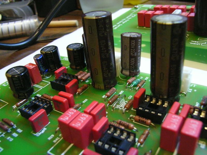
Which cap is this? Why does it need to be rated for 63 V?The 470 uF/63 V cap is too tall for 1 U rack!
Samuel
funkdrmr
Well-known member
Someone correct me if I'm wrong, but it looks like this cap is for C1, C14, and C15. 63v is specified for protection in case it's exposed to Phantom Power.
Hope that helps....I'm not sure what it does in the circuit, if that's the info you're after.
Hope that helps....I'm not sure what it does in the circuit, if that's the info you're after.
Samuel Groner
Well-known member
Indeed it does.It looks like this cap is for C1, C14 and C15.
Clever idea, but not well thought trough. C1 never sees mor than 18 V as U4 won't swing any higher than the rails. C14 and C15 won't see anything more than ~29 V due to R28 and R33 forming a voltage divider together with the phantom power resistors.63 V is specified for protection in case it's exposed to phantom power.
So: these caps can be 35 V (C1 even 25 V), which makes them substantially smaller and easy to fit in 1 U.
Samuel
khstudio
Well-known member
NOTE:
Cin1 & Cin2 (labeled on PCB) were added for phantom protection by Peter.
The originals didn't have them.
I didn't load them in mine... just jumped them.
#2
I'm not sure how C14 & C15 got so large a voltage. :?
The originals are 25v & that is what I used in my units as well.
I will fix this on the schematic... sorry.
khstudio
Well-known member
I Have updated my web site with the current Parts list, Schematic & Overlay
www.khstudio.us/DIY.htm
Just click on Nite EQ :wink:
www.khstudio.us/DIY.htm
Just click on Nite EQ :wink:
funkdrmr
Well-known member
Thanks, Kevin!
Can you provide some insight on my NE5532 / NE5534 question above? It seems my local store has the Fairchild model of these IC's in stock so I would like to pick them up.
I'm worried that there is a difference or preference between different brands like Texas Instruments, ON Semiconductor, Fairchild, etc...
Thanks again for all for this project. It's my first one and I'm having a BLAST sourcing and soldering everything up.
khstudio
Well-known member
[quote author="funkdrmr"]Thanks, Kevin!
Can you provide some insight on my NE5532 / NE5534 question above? It seems my local store has the Fairchild model of these IC's in stock so I would like to pick them up.
I'm worried that there is a difference or preference between different brands like Texas Instruments, ON Semiconductor, Fairchild, etc...
Thanks again for all for this project. It's my first one and I'm having a BLAST sourcing and soldering everything up.[/quote]
ANY of the RIGHT "TYPE = 5532 or 5534, will work fine.
The original used JRC 5532D & Signetics NE5534AN.
I happen to like the JRC's... there cheap & available.
BUT, I would have NO problem using others like the TI's.
If you read back earlier in the thread I get into the IC discussion & preference in more detail. :wink:
Good Luck :thumb:
funkdrmr
Well-known member
HAHA...I was JUST reading those posts when you replied.
Thanks! I think I'm just gonna stick with the components you used. I hope DigiKey shipping is fast!
Thanks! I think I'm just gonna stick with the components you used. I hope DigiKey shipping is fast!
bluezplaya
Well-known member
I have a question regarding the pushbutton switch and the 500k pots. Are there any substitutes for these at Mouser or Digikey?
Adam
Adam
funkdrmr
Well-known member
For the switch, I'm using P/N: 401-1223-ND from Digikey.
Similar threads
- Replies
- 3
- Views
- 418