hi!
I'm following actively this topic from weeks…
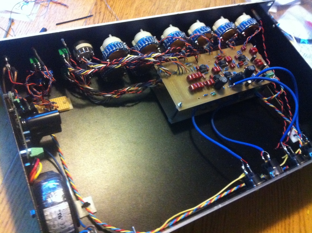
This is my build :
All pots are stepped with 0.5 Db steps with 23p rotary switches (from -5.5Db to +5Db). Thanks harpo for your exell file

I don't know if it works yet… I have to bring it to the studio for test, but so far so good : no smoke yet ;D
I have also to deal with the amber led's resistor values, they are killing my eyes (no issues with the red ones)
I'm planing to add the overload circuitry from there (thanks harpo again) :
http://www.khstudio.us/DIY%20PICs/CLIP%20CIRCUIT.bmp
just got a question :
on the peak schematic, signal is taken after pin 7 of U4
on my board done with Petter Cornell's PCB V2 1-6-7 it seems that the only pin 7 going to 470uf condenser ant then a 47r resistor (R29) is U6…
Anyone ever implement clip circuitry in their build?
Any help will be really appreciated!


![Soldering Iron Kit, 120W LED Digital Advanced Solder Iron Soldering Gun kit, 110V Welding Tools, Smart Temperature Control [356℉-932℉], Extra 5pcs Tips, Auto Sleep, Temp Calibration, Orange](https://m.media-amazon.com/images/I/51sFKu9SdeL._SL500_.jpg)


