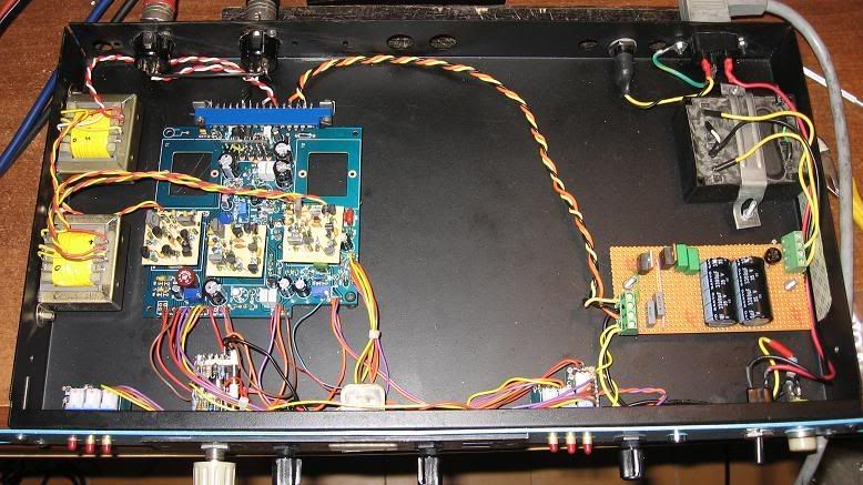
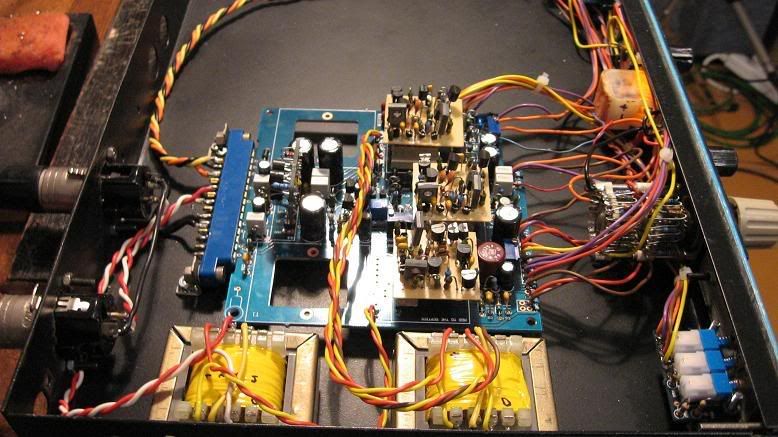
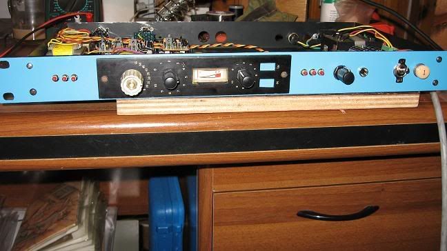
525 build thread

GroupDIY Audio Forum

Help Support GroupDIY Audio Forum:

This site may earn a commission from merchant affiliate links, including eBay, Amazon, and others.
525front.jpg


525inside.jpg


525insidedetail.jpg


the bypass switch does not show on your coloured schemo - i checked if it is implemented as in the original schematic but i dont see how..
??
 
the compressor now works - after i added R64 on the switch..... :green:

calibration goes well,but i have some dirt on the signal when compressing and even more with limiting.its not a lot but i think it should not be there.

when i have the out pot fully C.C.W (where it should be zero output) i can hear this distortion, and it increases as i turn up the input pot.

could it be a layout problem? (taking the negative input of A2 to ground eliminates it)
 
[quote author="mich"]the compressor now works - after i added R64 on the switch..... :green:

calibration goes well,but i have some dirt on the signal when compressing and even more with limiting.its not a lot but i think it should not be there.

when i have the out pot fully C.C.W (where it should be zero output) i can hear this distortion, and it increases as i turn up the input pot.

could it be a layout problem? (taking the negative input of A2 to ground eliminates it)[/quote]

Mine behave the same way. These things distort easily (part of their charm), but the more clockwise your rotary switch is, the less distortion appears to be present. So I'm thinking this is a fet anomaly.
PRR had something to say on the matter a while back. I'll see if I can find it.
PRR... "Because the FET sees the pre-limiting signal voltage, it overloads on strong signal. To make it work on typical line levels you have to attenuate the input, forcing a compromise with noise. It also is highly sensitive to FET parameters."

peter
 
So I'm thinking this is a fet anomaly.

if only i would have a couple more of them to swap..... :sad:

i was cheap ordering only one (10 pounds and 2 weeks to get here) - and now i have to pay for it :mad:
 
can someone pleas check if im doin it right?

the colour code for ed´s transformers:

primary - : Orange
primary + : Red


secondary - : black
socandary +: blue


secondary - : green
I
secondary +: brown

thanks a lot!!
 
this is what i wrote in the thread where you ordered the transformers:

[quote author="edanderson"]primary: red to orange
secondary1: blue to green
secondary2: brown to black [/quote]

so you've got the primary correct, but the secondary leads mixed up, i think.

ed
 
[quote author="edanderson"]this is what i wrote in the thread where you ordered the transformers:

[quote author="edanderson"]primary: red to orange
secondary1: blue to green
secondary2: brown to black [/quote]

so you've got the primary correct, but the secondary leads mixed up, i think.

ed[/quote]

thanks ed! ive read that, an i thought i should make it as you suggested, but than ive seen peter´s pictures of his unit and on these pictures it looks different from your explanation.

hmm and now i´m confused :?
 
[quote author="edanderson"]this is what i wrote in the thread where you ordered the transformers:

[quote author="edanderson"]primary: red to orange
secondary1: blue to green
secondary2: brown to black [/quote]

so you've got the primary correct, but the secondary leads mixed up, i think.

ed[/quote]

Trannies & FETs recieved, they look very nice.
Thank You!!
:grin:
 
OK boys... I think after attacking the crack, I've cracked the attack.
Leave C3 off the main board and move it to the attack pot wiper and take it to ground. If using the pot board, you'll have to seperate the pot pads and attach a wire.
Oh...lose that extra resistor too.

xx1zd2.jpg
 
[quote author="peter purpose"]OK boys... I think after attacking the crack, I've cracked the attack.
Leave C3 off the main board and move it to the attack pot wiper and take it to ground. If using the pot board, you'll have to seperate the pot pads and attach a wire.
Oh...lose that extra resistor too.
If I could upload a pic I would, but I can't.[/quote]

Peter is this with the original value pot ? was it 22k?
 
[quote author="peter purpose"]Oh...lose that extra resistor too. [/quote]

are you referring to R63?

ps =I am getting ready to test my 525 :grin:
 
what happens with this attack mod=? faster attack=?
an another quesion ..
should i connect the term jumper=?

i build a stereo version with controlls for each channel ..so i connected the mono strap on led pcb.. is this ok=?

thanks for help..

greetings, ludwig!
 
Back
Top