8 Channel, 3U NEVE 1073 completed

GroupDIY Audio Forum

Help Support GroupDIY Audio Forum:

This site may earn a commission from merchant affiliate links, including eBay, Amazon, and others.
When fixing the psu pcb to your case ground, just use 5mm standoffs to not flex the pcb in a convex or concave way. IM (and probably Joes) HO the heatsinking effect of your psu case seems better than an additional heatsink attached to the vRegs when mounted inside the non-vented psu case.
 
I just replaced the regs (and installed the new ones properly) and....it works!!!!

I can't express how relieved I am that it works! Thank you so much for taking the time! I am so grateful!!

Now I just need to wire up the trim, Go Between and DI...

Again, my sincerest thanks for your help and guidance here!!
 
Great to hear Indie!

useme2305 said:
shocking how no one noticed it before.

Actually, i did notice that they were bent the wrong way. I don't know why i didn't say anything...  ???

 
So I've been having this really weird issue of picking up a radio station for a brief amount of time a little after I shut the power off.

I recorded a short video of it here:

http://www.youtube.com/watch?v=YRGCNs-YyZw

Does it sound like I have a grounding problem? It's as if I've built an antenna somewhere. I've used shielded wire throughout the build. I also get 10ohm's from 0V to case, so I think I've got my PSU grounded properly. I've taken some pictures to show my wiring.

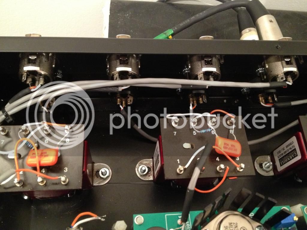
This first picture shows my wiring for the XLR inputs and outputs. The outputs are the bottom row and the inputs are the top row. I've twisted the inputs together for the run to each transformer in an effort to make the wiring a little neater. Was it ok to do this? It's shielded wire as listed in the BOM.
IMG_2748_zpsceb769db.jpg


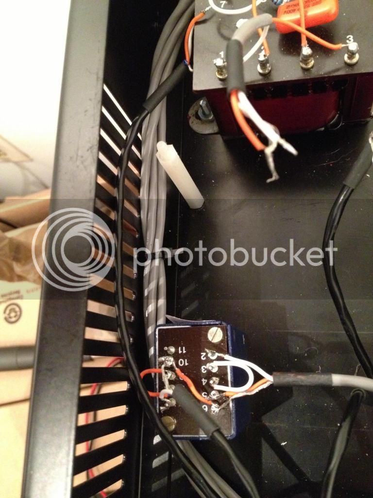
This is another picture of the twisting of the input wire. Could this be causing the issue?
IMG_2749_zpsdf316264.jpg


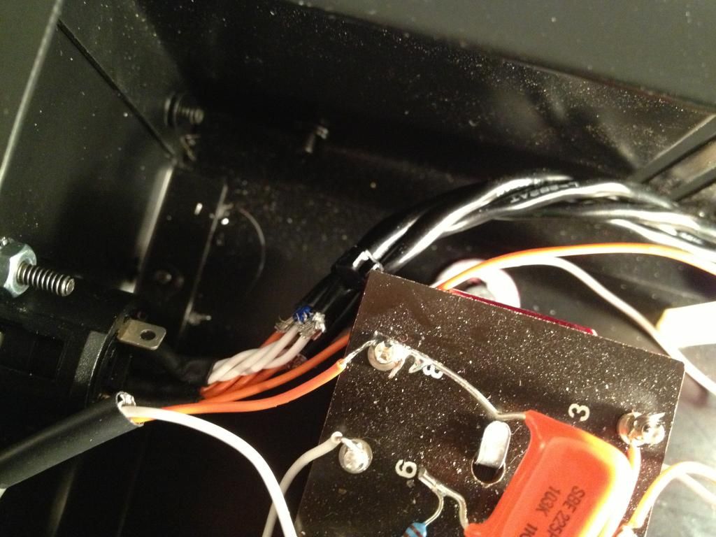
This is a picture of my 4 pin power input. I used 4 separate runs of shielded 2-conductor cable to power each board. I cut the shield at each end since it is not needed. I also twisted these together in an effort for tidy wiring. To me, it seems like the issue may be coming from the power side of things, since I get the radio interference when shutting the power off.
IMG_2751_zps5d8e56d1.jpg


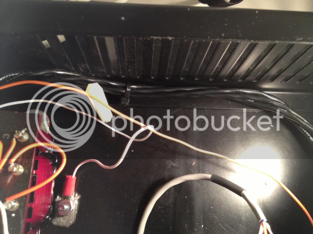
This is a picture of the twisting of the power. Each 2-conductor cable carries 0V and 24V to each of the four EZ1290 boards. Should I have not used shielded cable? I'm not using the shield, but is it acting as an antenna?
IMG_2752_zps9fe3c566.jpg

 
Check that the input transformer case has a good connection to chassis ground.
Do you have all the cable shields going to the audio ground on the pcb?
 
dmp said:
Check that the input transformer case has a good connection to chassis ground.
Do you have all the cable shields going to the audio ground on the pcb?

I will check the input transformer ground. I may need to scrape some paint to make a good connection.

Can you elaborate by what you mean concerning the cable shields going to audio ground? For the 24V and 0V (audio ground), I'm using a shielded 2-conductor cable for each board. There are 4 cables in total coming from the 4-pin connector. I'm using one conductor wire for the 24V and the other for the audio ground (0V). I don't have the shield connected to either end. Do I need to connect the shield wire to 0V in addition to the 0V conductor wire?
 
standard XLR treatment is two  ferrite beads on the input wires and two 10 pf caps from input wires to pin 1, you might try that,

 
I will check the input transformer ground. I may need to scrape some paint to make a good connection.
If you are screwing the transformer to the case the transformer should have a good ground. The screw holes are sufficient. I'd test it with a multimeter to be sure.
I just built another 2 channels and I tried them out before screwing down the transformer and I was getting buzz. With the transformer screwed down the buzz was gone.

Can you elaborate by what you mean concerning the cable shields going to audio ground? For the 24V and 0V (audio ground), I'm using a shielded 2-conductor cable for each board. There are 4 cables in total coming from the 4-pin connector. I'm using one conductor wire for the 24V and the other for the audio ground (0V). I don't have the shield connected to either end. Do I need to connect the shield wire to 0V in addition to the 0V conductor wire?
I was talking about the cables carrying the audio. The have two wires for the balanced signal (red & white) and a shield. I noticed the cable shields are not connected to the chassis ground tab on the XLRs, which is how I usually do it. You want one end of the cable shield connected to ground. That way, the cable shield acts like an antenna but just sends the noise to ground.  It is better to connect the cable shield to chassis ground. The ez1290 instructions say to connect to audio ground, which is going to be fine in most circumstances I think.
 
dmp said:
I was talking about the cables carrying the audio. The have two wires for the balanced signal (red & white) and a shield. I noticed the cable shields are not connected to the chassis ground tab on the XLRs, which is how I usually do it. You want one end of the cable shield connected to ground. That way, the cable shield acts like an antenna but just sends the noise to ground.  It is better to connect the cable shield to chassis ground. The ez1290 instructions say to connect to audio ground, which is going to be fine in most circumstances I think.

You're talking about input wires, right? According to the EZ1290 assembly instructions, the shield wire is not connected to either the output transformer, nor to pin 1 of the output XLR. Should I connect this shield to chassis ground?
 
There should be a ground tab on the XLR connector itself (looks like a little tab of metal sometimes with a hole in it) a lot of times they connect pin1 to that tab. Inputs should have pin 1 to shield and hooked up to the input tranny.  IEC ground to chassis and PS ground (not 0v).  You should be getting the 10ohm reading from 0v to chassis ground (not 0).
 
So I spent the afternoon trying all sorts of different ideas to chase this RF interference. I disconnected and untwisted all of the 24/0V wires, so that only one cable is hooked to one board. I scraped the paint from the case around the mounting holes for both the input and output tranny's, in an effort to get a solid ground connection. I connected the input shield to the XLR ground tab. I also connected the shield wire to the ground tab of the output tranny. All of this made no difference. It did not stop the RF interference.

I suspect this is originating from the PS, as it happens when I turn the power off. I am not using shielded wire in the PS, as I am under the impression it's not important in the PS. However, I think I have a lead...read below.

sr1200 said:
There should be a ground tab on the XLR connector itself (looks like a little tab of metal sometimes with a hole in it) a lot of times they connect pin1 to that tab. Inputs should have pin 1 to shield and hooked up to the input tranny.  IEC ground to chassis and PS ground (not 0v).  You should be getting the 10ohm reading from 0v to chassis ground (not 0).

Ok, I think this might be a potential source of the problem. From 0V to case (chassis ground/earth ground) I get a reading of 10.5ohm when there is NO LOAD. When there IS A LOAD, the reading from 0V to case is 37ohms.

I have my mains ground going to PSU case, as well as pin 2 (of the 4-pin connector) sharing the same grounding point. The PCB board is grounded via the mounting screw going to case. I'm using nylon standoffs.

What could this mean?
 
Ok, so I just found out that I needed to take those measurements with the power off. I re-measured everything with the power off. Here are my readings:

From 0V to PSU case, I read 10ohm.

From 0V to EZ1290 case, I get a reading between 6 to 8 ohms.

From Mains ground to PSU and from Mains ground to EZ1290 case, I get a reading between 6 to 8 ohms.

Have I done something wrong?
 
Yep. I ran a wire from the same spot where the mains is grounded to pin 2 of the 4 pin connector. Also, in my EZ1290 case, I ran a wire from pin 2 and attached to the case, thereby grounding both cases together. I'm still picking up the RF interference for a few seconds after I turn the power off.

I've been emailing Joe, and it seems that everything is ok with the PSU grounding.

My other option is to just learn to live with it. But I know it's not right. It's not supposed to be picking up an AM radio station when the power is draining.
 
CJ said:
standard XLR treatment is two  ferrite beads on the input wires and two 10 pf caps from input wires to pin 1, you might try that,

Could you elaborate on this? Would it be more beneficial to put the ferrite beads on the output wires after the output tranny, since it seems the noise is being picked up within the preamp or PSU circiut somewhere?
 
I'm not sure I've ever shut off mine with the audio still going through the monitors, so I'm not sure if I have the same behavior or not.
Still, it doesn't seem like it should do that. The only things I can think of are shutting off the power disconnects chassis and audio ground, or the 24v power rail starts picking up interference when it is shut off.
The ez1290 pcb has pretty hefty caps on the power rail on the pcb however, which makes this seem unlikely.
 
dmp said:
I'm not sure I've ever shut off mine with the audio still going through the monitors, so I'm not sure if I have the same behavior or not.
Still, it doesn't seem like it should do that. The only things I can think of are shutting off the power disconnects chassis and audio ground, or the 24v power rail starts picking up interference when it is shut off.
The ez1290 pcb has pretty hefty caps on the power rail on the pcb however, which makes this seem unlikely.

I was thinking that in practical use with the way I power on/off my gear, I would probably never hear this, or not often anyways. Still, I want to be certain that this isn't tied to some other underlying issue that could cause other problems. I hate the idea of not having these pre's 100% free from error.

That being said, I've torn apart pretty much everything trying to chase this down. I'm pretty much out of ideas, short of picking up a ferrite bead and slapping it on the output wire right before the XLR.
 
indiehouse Recording said:
I'm still picking up the RF interference for a few seconds after I turn the power off.
An analogy would be, complaining your stearing wheel is locked after you thru the drivers key out of the window of your still rolling car that you intend to stop.
Just turn the level of your monitors down when powering on/off connected gear.
 
I would say if you can turn the gain all the way up without any squealing and the sound is quiet and even without any buzz or interference, then you should go ahead and use them as preamps.
While you could have an underlying issue that is evident by the turn off thing, using them as preamps might be a better use of effort than chasing this turn off problem.
 
Harpo said:
indiehouse Recording said:
I'm still picking up the RF interference for a few seconds after I turn the power off.
An analogy would be, complaining your stearing wheel is locked after you thru the drivers key out of the window of your still rolling car that you intend to stop.
Just turn the level of your monitors down when powering on/off connected gear.

Excellent advice! That's the way I usually operate, especially in an effort to avoid the 'thump' this causes through my monitors.

dmp said:
I would say if you can turn the gain all the way up without any squealing and the sound is quiet and even without any buzz or interference, then you should go ahead and use them as preamps.
While you could have an underlying issue that is evident by the turn off thing, using them as preamps might be a better use of effort than chasing this turn off problem.

That's what my thought was when I woke up today. After chasing down my previous problem, I'm so ready to get these in my signal chain.
 

Latest posts

Back
Top