8 Channel, 3U NEVE 1073 completed

GroupDIY Audio Forum

Help Support GroupDIY Audio Forum:

This site may earn a commission from merchant affiliate links, including eBay, Amazon, and others.
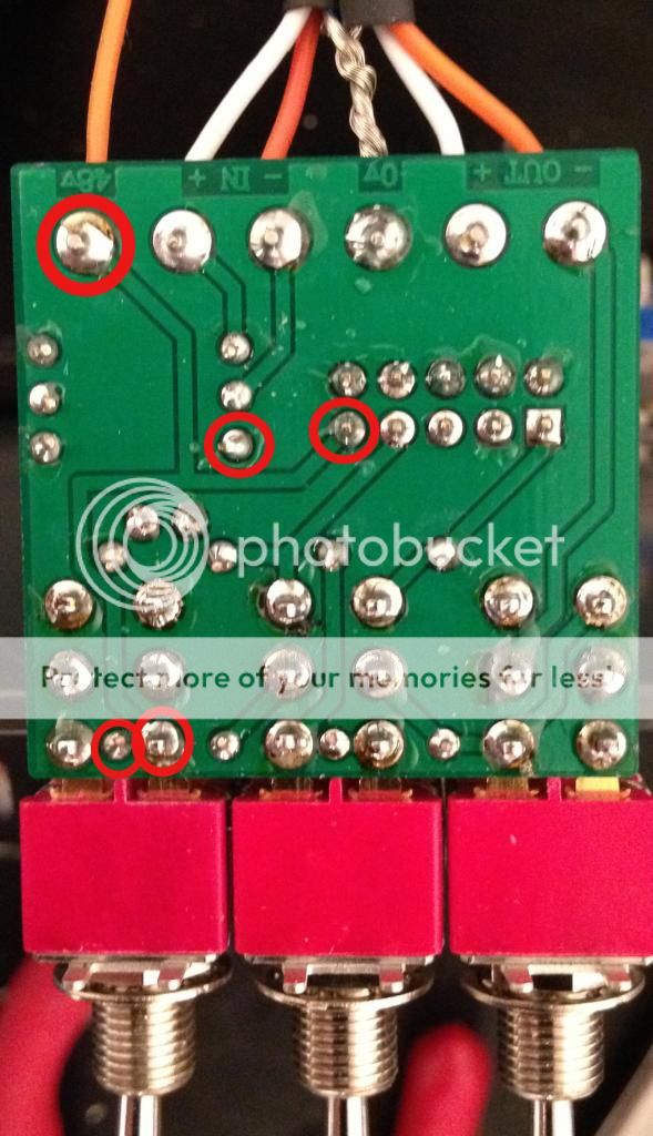
OK. So I woke this morning with a fresh head and thought about this some more. I thought that it's most likely a ground loop issue creating an 'antenna' that's picking up this AM radio station. I tore everything apart in my pre's and PSU trying to chase this down.

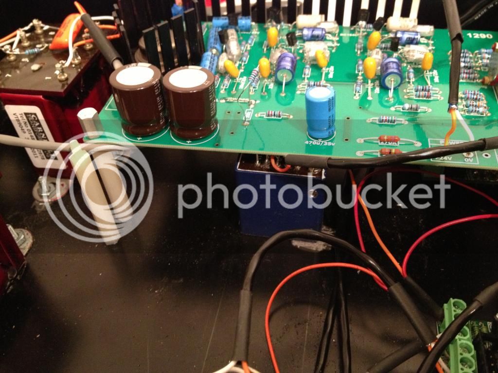
Then I got to thinking bigger picture. I have my Power Supply plugged into an outlet on a different circuit than my interface/speakers. When I use the same outlet as my interface/speakers, the RF interference is substantially less noticeable. It's definitely still there, but much quieter. At this point, I think I'm going to leave it alone. I still have to hook up my Go Between, DI, and impedance switch. However, if anyone ever has any ideas about how to completely eliminate the RF interference, I would definitely be interested.
 
I wanted to also get your opinions on the position of my input tranny under the board here. I tried moving it around, but didn't notice much of a difference. I've read that mounting them offset from the output tranny is a good thing, but there seems to be enough space between the two already. Is it ok leaving it here, or should I move it or offset it?

inputtranny_zps063a14e4.jpg

 
I agree if you don't have a problem, no need to move them. Problems will either be evident as oscillation, with the input picking up the output (positive feedback) or crosstalk between channels.
fwiw, the best orientation is to have transformers aligned perpendicular to each other, off axis. So the normal vector created by the winding structures of the two transformers are at right angles to each other, and don't project towards the other transformer.
I think your orientation actually has the normal vectors all parallel.
If you want to test crosstalk, put a high level signal through channel 1 and look at the output of channel 2

The best way to figure out your grounding is draw a complete connection diagram and post it.
Chassis, shields, connections, etc.
 
here is the xlr/ferrite thang,

lucked into a bunch of 1RU racks for10 bucks a piece,
favorite surplus store was going out of bidness, darn!

that had all these XLR's, some had 2 ea, some had 4, anyways,  now i have a drawer full of pre-wired jacks for DIY stuff,

i do not know where you could get the beads, 10 pf should be no problem, you can do in and outs this way,


Attachments

  • ferrite.jpg
    ferrite.jpg
    423.7 KB · Views: 61
CJ said:
here is the xlr/ferrite thang,

lucked into a bunch of 1RU racks for10 bucks a piece,
favorite surplus store was going out of bidness, darn!

that had all these XLR's, some had 2 ea, some had 4, anyways,  now i have a drawer full of pre-wired jacks for DIY stuff,

i do not know where you could get the beads, 10 pf should be no problem, you can do in and outs this way,

Awesome! Thanks for the great info!
 
Dang it!

Hook up my trim pot, per Martins diagram (post # 1399). All is well, works great!

Hooked up the Go-Between, Pad works fine, Phase works fine, but when engaging the phantom power, I smoked 3 of the 120R resistors in the Power Plant. I believe I remember Joe saying that burning these resistors means that 48V is shorting to 0V somewhere. So, if they didn't smoke when I turned the power on, then the short is not in the Power Plant, or in the 4-pin cable, as it would have shorted as soon as I turned on the PSU, right?

That leaves the short in the Go-Between, since the resistors burned when I switched the 48V toggle switch on. Kinda thinking out loud here. Am I on the right track?

I was thinking I may try to hook up one of the extra fuses I bought for the mains, and hook it up in line with the 48V coming from the 4-pin. So that when I'm trouble shooting, I'll burn the fuse, and not the resistors. Would this work?
 
use your ohm meter, there has to be a short somewhere,

a fuse will just blow and leave you right back where you started only short a fuse,

i would not expect a phantom circuit to draw more than 0.050 amps,

so your resistance should be at least 48/.05 = about 1000 ohms or more,

 
indiehouse, for troubleshooting grounding and shorting issues set your multimeter to the beeping continuity checker. it's VERY helpful for quick troubleshooting in various spots in a projects and yields in results quickly.
 
Thanks for the tip on using my DMM! That makes total sense now.

So, if I'm shorting out 48V to 0V, which wire is 0V on the Go-Between? Positive (hot), Negative (cold), or shield?

I'm thinking shield, right? Or am I thinking about this the wrong way?

Thanks again for all the awesome guidance! You guys have been super helpful and I'm learning so much!!
 
I did a continuity check from 48V to all points on the Go-Between with the 48V toggle engaged. I figured if it was shorting out somewhere, my DMM should reveal the continuity, right?

Here are all the points where continuity was achieved. Oddly enough, 0V wasn't one of them. Are these points supposed to have continuity with 48V?

GoBetween_bottomcontinuitycopy_zps70bbee1d.jpg
 
Most likely fault might be the 10uF cap on the GoBetween fitted the wrong way round. If so and the paralleled 120Rs on the psu didn't blow faster, the 470R might be blown as well and as followup phantom voltage now doesn't arrive at the 470R/6K8s/cap+ junction anymore.
 
Harpo said:
Most likely fault might be the 10uF cap on the GoBetween fitted the wrong way round. If so and the paralleled 120Rs on the psu didn't blow faster, the 470R might be blown as well and as followup phantom voltage now doesn't arrive at the 470R/6K8s/cap+ junction anymore.

I was really hoping that would be the answer!

Just checked, and the cap is definitely installed
the correct way.
 
So there is no short at the GoBetween that you tested.. The 4K6 is the sum of the voltage setting resistors R1+RV1 on the PowerPlant pcb. Check the other GoBetweens as well.
 
Update: I replaced the burnt resistors in the power supply, unhooked the Go-Between from the LED and used my DMM to try to find a short between 0V and 48V. I couldn't find anything.

On a hunch, I wondered if the two legs of the Go-Between that were connecting the LED were somehow shorting out when the LED was installed. After all, aren't these legs 0V and 48V, required for the LED to function?

Anyways, I tested out the phantom power without the LED...worked like a charm! After installing the LED...still works, nothing fried!

Granted, nothing is really mounted to the case, so I'll need to be extra careful when stuffing everything back.

I can't tell you how relieved I am.

So, 1 out of 4 boards is fully operational...

I wired up the impedance switch as well. It seems to be working pretty smooth, but I want to be sure. I followed the diagram below, and wanted to double check with you guys that this is the correct way. XLR -> Go-Between -> Impedance Switch -> Tranny.

Am I right on this? I installed this switch to exchange from a connection in series (1200 ohms) to the input transformer or to parallel one (300ohms), from what I understand.

I measured from the input XLR (pins 2 and 3) and I got 12.2 ohms, switched the toggle and got 46.7 ohms. This seems a long way of from 300/1200.

I also get continuity between XLR pin 2 and 3 on one side of the toggle, but not the other.
Am I able to measure this to ensure that I'm getting 1200 ohms and 300 ohms? Where do I measure?

2dahnro.png
 
congrats on getting the phantom up!

your ohms for the xfmr look good,

let us say you hve 24 ohms for each pri coil,

with 24 in series you get 48, now when you run the 300 ohm setup, the coils are in parallel,

anytime you have 2 parallel resistors of same value, the calc simplifies to just dividing 24 ohms by 2 = 12 ohms so everything is cool so far.

use the DMM on ohms and connect to pins 2 and 3.

you should get 12 and 48 ohms again.

i bet the 48 ohms was too much for your continuity checker to say yes,

but it liked the 12 ohms ok, so everything looks go for takeoff at 08:00.

that LED across the 48 volts, i figure it is a 48 volt LED or a lightbulb, unless you have a series resistor on a regular LED?

otherwise the LED would have smoked like a chimney, get me?


Back
Top