You are using an out of date browser. It may not display this or other websites correctly.
You should upgrade or use an alternative browser.
You should upgrade or use an alternative browser.
Access-312 Build Thread
- Thread starter thesystem
- Start date
Help Support GroupDIY Audio Forum:
This site may earn a commission from merchant affiliate
links, including eBay, Amazon, and others.
Neily
Well-known member
http://classicapi.com/catalog/product_info.php?cPath=51_133&products_id=237
Hey guys... Does anyone know if this wicked stepped gainswitch bundle from classic api will work in place of the 10k rev log pot on my access?
I have these on my VP312s modules and i love them, I was wanting to swap my alpha pots on my access312s to stepped grayhills. Would I have to change anything on my access boards to do this?
Thanks for any help\advice...
3nity
Well-known member
Hi Neil.
Theres Yes you can use that.
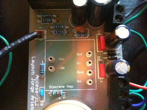
What you have to do is change 2 resistors and 2 caps and youre set.
R5 is 20K, C7 is 120pf and R4 should be 220R and C6 should be 250uf/6v.
Thanks
Theres Yes you can use that.
What you have to do is change 2 resistors and 2 caps and youre set.
R5 is 20K, C7 is 120pf and R4 should be 220R and C6 should be 250uf/6v.
Thanks
3nity
Well-known member
For anyone who might be interested i have 4 boards waiting to be shipped.
Let me know if anyone is interested.
Thanks.
Let me know if anyone is interested.
Thanks.
band_master
Well-known member
- Joined
- Mar 14, 2011
- Messages
- 68
hey guys,
i am finishing up my second unit and am having a little trouble with channel 3. at first i had R4 and R5 backwards as per bomv2. all channels passed audio, though, with a clean signal only the gain pot did nothing. After fixing R4 and R5 channels 1, 2, and 4 work perfectly but channel 3 has very low output until the gain pot is maxed. And then the output seems a bit distorted. After I max out the gain pot it takes a second or two before the volume increases. Anything less than full volume and the signal is barely audible. here is some troubleshooting i did:
i checked the pot with a ohm meter and it is functioning.
i bridged 1-2 on the gain pins on the board and I get the distorted signal like when the gain is pot is maxed out.
i tried swapping op amps and no change so i guess those can be ruled out.
i installed a new connector cable between the board and the gain pot, no change.
i tried using a different set of xlrs to the board and still getting the same thing so its not those cables.
i think maybe a component has gone bad or i might have damaged the audio transformers? I checked for continuity at all points on the molex connectors and everything looks good. any ideas of where to go from here?
thanks!
BD


3nity
Well-known member
Can you compare some values vs a working channel?
check volts first...
check volts first...
band_master
Well-known member
- Joined
- Mar 14, 2011
- Messages
- 68
right on. thanks, Jorge! i checked the voltages at the sockets for channels 3 and 4.
V+: 15.68 on channel 4, 15.7 on channel 3
V-: -15.73 on both channels
Gnd: 0v on both channels
I am getting 0v on +in, -in, and Out on both channels. Where else should I be looking?

BD
V+: 15.68 on channel 4, 15.7 on channel 3
V-: -15.73 on both channels
Gnd: 0v on both channels
I am getting 0v on +in, -in, and Out on both channels. Where else should I be looking?
BD
3nity
Well-known member
triple check all you resistors.
and can you try another pot?
Thanks
and can you try another pot?
Thanks
band_master
Well-known member
- Joined
- Mar 14, 2011
- Messages
- 68
all resistors color bands match between channel 3 and 4. tried another pot, same issue. is there a way to check the transformers with a meter?
3nity
Well-known member
If you really want to check transformers.
Measure with Ohm selected meter between primaries, then secondaries.
Thanks
Measure with Ohm selected meter between primaries, then secondaries.
Thanks
band_master
Well-known member
- Joined
- Mar 14, 2011
- Messages
- 68
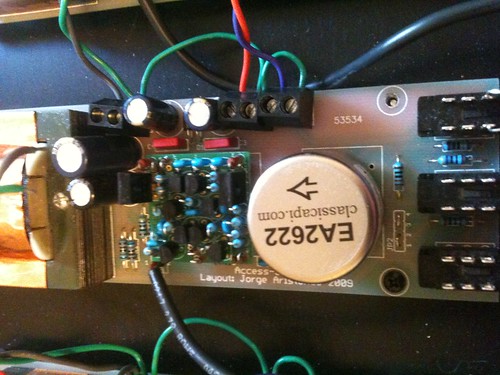
OK, I checked the Classic API website for specs on the EA2622. Here is what I am getting when testing the xformer seated in the PCB:
primary: 1.55k ohm
secondaries: 29.2 ohm
and for the EA 2503:
primary: 8.93 ohm
secondaries: 8.93 ohm
these are actually the same readings i am getting on a working channel. do these results indicate anything? should i be testing under load? for what it's worth i replaced R4 and R5 also reheated all solder joints and still have the same problem. i have noticed recently that it can take several seconds at full gain before the volume bumps up to audible but distorted levels. is it time to start pulling resistors?
cheers,
BD
band_master
Well-known member
- Joined
- Mar 14, 2011
- Messages
- 68
UPDATE: i checked all in-circuit resistor values with a working channel and everything is consistent. tried swapping out C7 but now I am getting no output at all from the channel. the only thing i hear is the op amp squealing when i power down. the squeal actually used to be a bit warbly on this channel and now it seems normal. I am using a 1500uf/6v cap at C6 as per bom V1. should this be changed to 470uf/16v as per bom v2?
3nity
Well-known member
dont change it ...its all good .
Hey all,
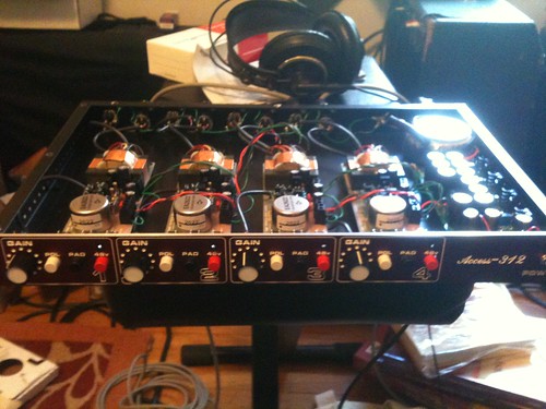
So I built 4 of these great boards for a buddy and at first everything sounded really good. But then after some testing I noticed that one of the boards had a slight hum that I couldn’t get rid of. I initially thought it was power related, mainly because it was at the end of the power chain. So in an effort to fix the low hum I powered each board from the PS board separately. That didn’t do a damn thing, long story short I just left it and figured it was within the noise floor. We recently used them on a recording and over time the hum got louder and louder and we eventually stopped using it The sound doesn’t change with the gain and it doesn’t fallow the opamp. I swapped on of the others, I haven’t started replacing components yet, thought I would ask on here first.
Any help would great!!
Eric
So I built 4 of these great boards for a buddy and at first everything sounded really good. But then after some testing I noticed that one of the boards had a slight hum that I couldn’t get rid of. I initially thought it was power related, mainly because it was at the end of the power chain. So in an effort to fix the low hum I powered each board from the PS board separately. That didn’t do a damn thing, long story short I just left it and figured it was within the noise floor. We recently used them on a recording and over time the hum got louder and louder and we eventually stopped using it
Any help would great!!
Eric
is it on all 4 boards or just the one closest to the power transformer?
band_master
Well-known member
- Joined
- Mar 14, 2011
- Messages
- 68
hey guys,
just wondering if anyone out there has an extra access 312 board they'd be willing to part with. 3nity has been great helping troubleshoot my problem. right no the PCB works with some op amp design and not others. unfortunately there are no more boards available, so just thought i would check. If you have an extra laying around you're not going to get around to send me a PM!
cheers,
BD
shabtek
Well-known member
Eric... can you move the power xfmr or run in a temporary external p.t. to rule out proximity of iron(s)--I prefer external p.s. for pres.
okgb
Well-known member
If you have them on connectors , can you swap boards into different positions ?
does the prblem follow the boards or stay in that position ?
all the solder joints look good ? grounds & capacitors ?
does the prblem follow the boards or stay in that position ?
all the solder joints look good ? grounds & capacitors ?
Similar threads
- Replies
- 1
- Views
- 1K
- Replies
- 3
- Views
- 932
- Replies
- 6
- Views
- 702
- Replies
- 11
- Views
- 8K
- Replies
- 6
- Views
- 2K


