Analysis of Sweepable Midrange control

GroupDIY Audio Forum

Help Support GroupDIY Audio Forum:

This site may earn a commission from merchant affiliate links, including eBay, Amazon, and others.

Matador

Well-known member
Joined
Feb 25, 2011
Messages
3,097
Location
Bay Area, California
I've been studying the following schematic:

parametric_mid_eq.gif


I've been trying to ascertain the design equations for the parametric midrange portion of the control.  I have some design equations for the Baxandall bass and treble sections but have been struggling with the circuit analysis for the topology around IC1B.

What I'm interested in is:

1) Frequency points for the poles and zeroes that define the bandpass region (I assume the equations should contain two poles and two zeroes to define the pass band).
2) Maximum gain at the mid center frequency
3) Q of the filter
4) Gain outside the pass band

So let's assume for analysis purposes that R11 is dialed to the top (maximum boost), and that R10 is dialed fully 'down' (so that R10 disappears from consideration for the moment).

The (roughly) equivalent circuit is this (omitting the effect of R11 for the moment):

300px-Op-Amp_Differential_Amplifier.svg.png


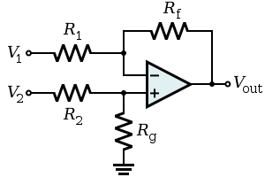
With V1 = V2, R1 = R8, Rf = R9, and the complex impedance of R12 and C5 being equal to R2, and the complex impedance of R13 and C6 being equal to Rg.

So question #4 above is the easy one.  At DC, C5 and C6 are open, which means the non-inverting input is tied to ground through R13.  At 'high' frequencies (f >> the pass band), the non-inverting input is grounded through the short that is C6.  In either case, the circuit reduces to a standard inverting stage with R8 and R9 defining the gain of the stage.  So if we want 0dB gain (unity) outside of the pass band, then R8 must equal R9.

Doing the nodal analysis of the differential amplifier yields the following equation for the gain:

VOUT/VIN = - (Z1*Zg - Zf*Z2)/(Z1*(Z2+Zg))

I think this result is correct as I see a similar equation posted in textbooks for this topology.

Here is where it get's nasty.  If I let Z2 = (R12 + 1/s*C5), and Zg = R13/(1+s*R13*C6), I get this simplification for the transfer function in the Laplace domain:

transfer.jpg


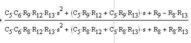
And here is the solution for the poles:

solution1.jpg


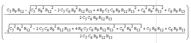
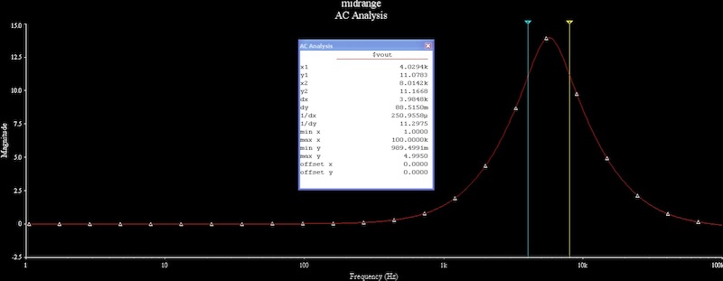
So the brute force mathematical approach yields complicated answers, but my gut tells me the overall approach should be easier.  Just by inspection, the combination of R12 and C5 should form a zero, and the combination of R13 and C6 should form a pole.  Just plugging in the numbers, I get a -3db point for the zero and -3db point for the pole that match the simulation exactly.  So the two turn frequencies are:

f1 = 1/(2*PI*R12*C5)
f2 = 1/(2*PI*R13*C6)

Center frequency should be (using geometric mean principle):

SQRT(f1 * f2)

which again matches the simulations exactly.

Is there an easier way to go about this without pre-guessing the final answer?

 
Wow, you're hurting my head with all that math.. Perhaps search for "wein bridge EQ topology". This has been around for quite a while.

I used that topology in the old AMR console I did decades ago, but I mostly "borrowed" that EQ design from the engineer doing the Live Peavey SR console (MkVIII) and I don't know where he got it. I dialed it in empirically for a different Q more appropriate for recording, and IIRC there was an interaction between the Q and max boost/cut.

The circuit I used had end limit Rs in series with the boost/cut pot, and we tooled the R10A and R10B pot sections into a custom single section with two partallel screened resist paths that were shunted by a single wiper, so the whole EQ section could be controlled on one concentric pot shaft with the outer shaft/knob controlling frequency and inner shaft/knob for boost/cut. 

BTW, as i recall it's a very sweet sounding EQ, the noise gain of the opamp is low, so the EQ delivers low noise, low phase shift, and low distortion.

JR
 
I can find many references to the topology, but no design equations.  There's some anecdotes from Mackie about Cal Perkin's 20 page analysis of the circuit and I can see why...it's a simple topology but a challenge on the formal analysis side.

I also see the drawing I posted is not quite correct:  the midband gain pot should be in the feedback path from output to input, not to ground.
 
Matador said:
I can find many references to the topology, but no design equations.  There's some anecdotes from Mackie about Cal Perkin's 20 page analysis of the circuit and I can see why...it's a simple topology but a challenge on the formal analysis side.
Indeed! It's even more complex than formal analysis of the baxendall EQ. I remember about 30 years ago I had done it because I wanted to make the frequencies sweepable on LF, MF and HF. I scribbled dozens of pages while commuting and got results that were indicative at best (but isn't it always the case).
I think you should use a simulation software - unless you have to do academic work - you would learn a lot about the Wien EQ, in particular its limitations! Making Q variable has always been a challenge with this topology. Many commercial implementations use different values for C5 and C6.
 
Yup,  c5 and C6 were different in my version of the circuit roughly c5=5x c6.

For full parametric EQ, with independent adjustment of different parameters, state variable is more popular.  For fixed Q the wien bridge is less opamps and probably cleaner, while there are subtractive approaches to SVF that can be low noise gain too.

JR
 
I would like the Q to be fixed, which is why I gravitated to this topology since it does what I need with a single op-amp.

Picking a Q that gives the two turn frequencies exactly one octave apart:

Q = (fc)/(fhigh - flow)

Where fc = SQRT(fhigh * flow)

Substituting it in I get that Q should be SQRT(2) or 1.414 to get exactly one octave in the passband.

In order to get this (assuming that R1 = R2), I need C2 = 1/2 C1.

So my equations say that for R12=R13=3.9k, R8=R9=22k, C5=10nF, C6=5nF, I should get:

Low turn = 4KHz
High Turn = 8KHz (exactly one octave up!)
Center = 5.77kHz

Simulation matches my equations exactly so I think I'm on the right track:

midrange1.jpg


Simulation shows 14dB of gain at the center frequency:  that's the main piece I'm missing so back to the equations....

Filter theory says a circuit based on R's and C's should provide a bandpass transfer function that looks like:

midrange-transfer.jpg


But my nodal analysis keeps ending up with an s2 term in the numerator....

Back to the drawing board!
 
First, you have to understand that an EQ is not a standard filter. Standard filters are characterized by infinite attenuation asymptotic curves. An EQ has asymptotes to unity-gain.
An EQ is a biquad, defined by a fraction, of which the numerator AND denominator are polynomials.
So you have to forget about the academic Q => BW relationship (it does not work when the amplitude of boost/cut is less than 3dB).
The standard relationship works more or less only when the amplitude of boost/cut is high enough (min 12dB).
 
abbey road d enfer said:
First, you have to understand that an EQ is not a standard filter. Standard filters are characterized by infinite attenuation asymptotic curves. An EQ has asymptotes to unity-gain.
An EQ is a biquad, defined by a fraction, of which the numerator AND denominator are polynomials.
So you have to forget about the academic Q => BW relationship (it does not work when the amplitude of boost/cut is less than 3dB).
The standard relationship works more or less only when the amplitude of boost/cut is high enough (min 12dB).

Makes sense, and I was more trying to glean understanding from other analysis factors rather than trying to get direct answers.

What would be a good strategy to get a handle on the pass-band gain?
 
Hi,
I think it helps if you break the circuit down a little.

Consider the over-arching topology i.e. the inverting op-amp, a pot mixing the input and output into a processing stage which I'll call G(s) or simply G (i.e. potential divider formed by R12,C5,R13,C6). 

If you do the math, the expression which results is the following (assuming R8=R9=R11=1ohm to make the theory easier):

H(k) = - (2G(1-k) - 1) / (2Gk - 1), where k is the pot adjustment (0..1)

So at one end you get H(1) = 1/(2G-1), the other end, H(0) = (2G-1) and in the middle H(0.5)=1

Therefore we get the characteristic symmetrical cut-boost behaviour.

No on to G(s).  Again doing the math on paper you get (I've used R1,C1,R2,C2 for R12,C5,R13,C6 resp.)


      s/C2R1
-------------------------------------
s^2 + s(1/C2R2 + 1/C1R1 + 1/C2R1) + 1/C1C2R1R2


Now assuming we are at one ond of the pot travel (k=0) and Plugging G(s) into H(s)

H(s) = 2G(s) - 1, we get:


s^2 + s(1/C2R2 - 1/C2R1 + 1/C1R1) + 1/(C1R1C2R2)
------------------------------------------------
s^2 + s(1/C2R2 + 1/C2R1 + 1/C1R1) + 1/(C1R1C2R2)

and now a clearer picture emerges.

This is a ratio of 2 polynomials with differing Q values.
i.e.

s^2 + wo.s/Q1 + wo^2
----------------------
s^2 + wo.s/Q2 + wo^2


The magnitude of one of these polynomials at wo is given by:

|G(wo)| = wo^2/Q


Therefore the ratio of the gains at wo is:

Q1/Q2

Relating to component values we get:

|H(wo)| = C1R1 + C1R2 + C2R2
          ------------------
          C1R1 - C1R2 + C2R2


Restoring actual circuit component references and assuming R12 = R13 we end up with the following design equation for gain at wo:

C5 = C6*(gain - 1)/2


for a gain of 5 i.e. 13.98dB we have:

C5 = 5nF*(5-1)/2 = 10nF

Hope this helps.

P.S. I did do some work on gain-Q dependency as part of some DSP work for a digital console if you or anyone else is interested (I'll have to dig out my note though!).

Cheers,
Dave.

<edit> worth pointing out that this approach conveniently ignores the loading of G(s) on the pot when not at either extreme so it's not an exact analysis for values inbetween.
 
Not to hijack this thread and this is kind of related.  Dave, do you have any thoughts on how to define "Q" for bell (peak/cut) EQ sections? For years we have struggled with analog 1/3rd octave graphic EQ from different manufacturers that exhibit different Q despite nominally all being the same.  This has come under more scrutiny with DSP and the promise of accuracy and repeatability. Manufacturers offer factory preset loudspeaker crossovers, and while the passband filters track reasonably accurately, corrective EQ added on top of those well defined HP/LP filters tend to exhibit different Q depending on the individual designer's personal definitions when loaded into different DSP platforms**.

Do you have any insight into a standard definition for Q in that context? 

JR

** There is a longer list of errors between different DSP platforms, but I am specifically asking about Q for bell EQ sections.
 
I don't know of a standard definition for Q in bell filters but the one I have used is as follows:
Q is the normal measure of centre frequency and -3dB bandwidth with gain set to maximum boost (or cut) (+/-18dB in our case)

So the Bell filters have a Q as specified by the Q control when the cut/boost is at maximum.  As the cut/boost is reduced, the Q reduces so a more gentle curve occurs at lower cut/boost levels.  Our customers generally prefer this type of gain/Q response but as the Q is adjustable anyway you can always get what you want at a given setting.  We don't do graphic EQ.

The bell filter as essentially two cascaded 2nd order filters each with a different Q, so the concept of Q for the combination is technically a bit if'y.

The "numerator filter" starts of at a magnitude of wo^2, dips around wo (acording to the Q value) and then tends to an upwards lead/differentiator +40dB/decade w^2 response.  The "denominator filter" starts at 1/wo^2, rises around wo in a slightly different manner according to a different Q value and then tends to a -40dB slope.

Bell%20response.JPG

 
Yup, typically theres an underlying BP section that has a classically defined Q. At max boost/cut, that BP is large and in charge.  Unfortunately different topologies (or implementations), deliver different results over the entire range of boost/cut. 

I'm probably repeating myself, but I approached the AES standards body a few years ago with this issue, and they agreed there is a problem, but no solution has been forthcoming (AFAIK I haven't checked lately).

Right now digital DSP platforms are failing to deliver what DSP is supposed to be best at, repeatable accuracy. They are surely repeatable, but without a standard, when brand X says +2dB at a Q of xyz, it doesn't translate to the same output as when brand Y says that.

This is only one of several sources of error between platforms, but one that should be readily resolvable with a uniform standard. I don't care how we do it, as long as we end up with only one definition for it. The rest of the errors are more subtle and should work out as the technology matures.

JR

 
There's been endless discussions about this suject. IMO, Q is a well understood and defined parameter, which just happens not being usable for equalizers.
Davebungo's definition of BANDWIDTH is pretty close to what I came to consider a sensible approach, making measurements and perception consistent.
I reckon the bandwidth notion is sufficient for describing this aspect of equalization.
Trying to force the notion of Q in equalizers is scientifically wrong and counterintuitive. Good proof is that nobody agrees on a common definition...
I think it is our duty, as veterans/mentors, to prevent young eager people like the OP to waste their time erring on such subjects.
 
abbey road d enfer said:
There's been endless discussions about this suject. IMO, Q is a well understood and defined parameter, which just happens not being usable for equalizers.
Davebungo's definition of BANDWIDTH is pretty close to what I came to consider a sensible approach, making measurements and perception consistent.
I reckon the bandwidth notion is sufficient for describing this aspect of equalization.
Trying to force the notion of Q in equalizers is scientifically wrong and counterintuitive. Good proof is that nobody agrees on a common definition...
I think it is our duty, as veterans/mentors, to prevent young eager people like the OP to waste their time erring on such subjects.

We can agree on a definition among us that seems sensible, but this does not resolve the reality that there are multiple definitions currently in use across different DSP platforms (actually this disparity goes back long before DSP).

However we may feel about it, Q is the third parameter widely used by the entire industry to characterize bell (peak/cut) EQ along with the amount of boost/cut, and center frequency.

This could be resolved, by naming the sundry different flavors of Q when used in that (bell) context with translation relationships between them. Different flavors of Q seems better to me than one Q, that doesn't mean the same thing to all manufacturers.

This has utility beyond loudspeaker crossover factory presets.  This also very much affects any attempt to precisely characterize a specific console EQ (beyond simple shelving or band-stop sections).  Every console maker specifies Q for their boost/cut EQ, but what that Q actually delivers (and sounds like) will vary if replicated on a different platform using a different definition for that Q.

This seems worthy of clarification to me. It actually deteriorates faith in the scientific method, if two EQs that supposedly spec out the same, sound different in use. They sound different because they are different. 

JR

PS: People will pursue whatever they want, despite our judgements. I can only try to manage the presentation of facts as I know them.
 
I agree that we should try to have a common definition of BW. Defining Q is vain because it is of no use in calculations related to EQ's, analog or digital.
The silliest thing I see is DSP engineers writing EQ algorithm using the formula or one of the online calculators, which all give wrong results.
In addition, when I manipulate the "Q" knob on an equalizer, I have a pretty strong idea of what relative bandwidth I want to interfere with; my ears don't tell me "I hear a 3kHz hump with a Q of 8".
 
Q actually has a well defined meaning.  It is the reciprocal of the underlying LP filter response at the turnover frequency.  Dave's use in his examples is correct.

What is ill-defined is 'bandwidth'

At high Q (big boost/dip)    Q = centre_frequency / -3dB_bandwidth

But what if the boost/dip is less than 6dB?

I use Moorer's definition.  He has a good Digital Parametric as

presence() from "Manifold Joys of Conformal Mapping"

if boost/cut > 6dB,  bw is 3dB points
else from frequencies for half boost/cut
__________________

For Matador's original query ..  I wrote my own circuit analysis programme to avoid error prone complex algebra which hurt my head.  I used to do a lot but would never go back cos I nao kunt kont, reed orr rite.

Playing with a circuit analyser gives you more insights & quicker too.  I've come up with new useful circuits by playing that would never have emerged from staring at the maths.
 
ricardo said:
I use Moorer's definition.  He has a good Digital Parametric as

presence() from "Manifold Joys of Conformal Mapping"

if boost/cut > 6dB,  bw is 3dB points
else from frequencies for half boost/cut
__________________

That is logical and eminently usable in the digital domain where you can tweak an EQ to deliver a constant Q wrt boost/cut, no matter however we decide to define that.. How does that approach map out wrt common analog EQ topologies? or is this yet another flavor of Q?

JR

 
ricardo said:
Q actually has a well defined meaning.  It is the reciprocal of the underlying LP filter response at the turnover frequency.
A meaningless meaning, because it doesn't relate to the actual performance of the EQ. It is just a mathematical by-product. Remember that the notion of Q in an RLC circuit has a practical meaning for evaluation of some component parameters. Trying to push its usage in a different context is counterproductive.
Dave's use in his examples is correct.
Which leads him to no practical conclusion.
What is ill-defined is 'bandwidth'

At high Q (big boost/dip)    Q = centre_frequency / -3dB_bandwidth

But what if the boost/dip is less than 6dB?

I use Moorer's definition.  He has a good Digital Parametric as

presence() from "Manifold Joys of Conformal Mapping"

if boost/cut > 6dB,  bw is 3dB points
else from frequencies for half boost/cut
Which means that for the same circuit implementation, BW will vary depending on the amount of B/C ? What is the practical usage of such a parameter?
 
abbey road d enfer said:
A meaningless meaning, because it doesn't relate to the actual performance of the EQ. It is just a mathematical by-product .... Trying to push its usage in a different context is counterproductive.
Err..hh.  Does anyone have a more productive definition of Q?  To be specific ...

LP filter  LP(s) = 1 / [ (sT)^2 + sT/Q + 1 ]
BP          BP(s) = s / LP(s)
HP          HP(s) = s^2 / LP(s)

A parametric is a +/- combination of BP(s) and a linear channel.

This Q is also  EXACTLY that which applies to common RLC circuits for the above and their component values.

Where does this definition of Q fail to meet "common" definitions used in EQ?

Answer: If the boost/dip is less than 6dB

What are these "common" defns.?

If (the precisely defined) Q is hard to relate (not understandable by the unwashed masses), perhaps manufacturers shouldn't use it.

If BW is used, what's wrong with Moorer's defn.?  What are the "common" definitions?

Which means that for the same circuit implementation, BW will vary depending on the amount of B/C ?
You got a better defn.?  One that doesn't jibe at less than 6dB boost/cut?
 
abbey road d enfer said:
Davebungo's definition of BANDWIDTH is pretty close to what I came to consider a sensible approach, making measurements and perception consistent.
Duu..uh!  I no i kunt reed but war iz dis definition?

And IIRC, Moorer was on the AES committee discussing this  (maybe chief) which is why he produced his definition.
 
Back
Top