Analysis of Sweepable Midrange control

GroupDIY Audio Forum

Help Support GroupDIY Audio Forum:

This site may earn a commission from merchant affiliate links, including eBay, Amazon, and others.
ricardo said:
abbey road d enfer said:
Davebungo's definition of BANDWIDTH is pretty close to what I came to consider a sensible approach, making measurements and perception consistent.
Duu..uh!  I no i kunt reed but war iz dis definition?

And IIRC, Moorer was on the AES committee discussing this  (maybe chief) which is why he produced his definition.
The definition I like (and I'm not the only one, several highly-regarded equalizer designers like it too), is to define the corner points as the points where the boost/cut is a specific fraction of the maximum B/C. For example, KT DN27 (grandaddy of graphic eq's) provides +/-12dB boost/cut, the +/-3dB points are located 1/6 octave away from the center frequency. Terry Clarke's definition was that when you move the 1k fader, the auditive result affects only the 1/3 octave band centered at 1k. So the DN27 corner points are defined 1/4th the max B/C. I know this is arbitrary, because if the EQ has +/- 15db B/C, the corner points will change, but anyway the definition of bandwidth in an EQ cannot be anything else than arbitrary. Obviously, when KT moved from real inductors to pseudo-gyrators, they had to change their definition, because they couldn't achieve the same selectivity.
Some designers define their corner frequency as the points where the B/C is half the maximum B/C. It is no less arbitrary, but also it doesn't sit as well in terms of auditory sensation. That makes for much wider filters. Many sound engineers think that a 1/3 octave EQ obeying this definition is too wide.
James Moorer, as brilliant as he is, may have been tempted to let mathematics take over practicality. Remember his world is constituted of 0's and 1's!
The "Q" parameter has the advantage of being directly usable in the calculation of coefficients in digital EQ's.
In digital impementation, the coefficients are governed by a single parameter alpha. When Q is the design parameter, the formula is alpha = sin(w0)/(2*Q). When BW is the design parameter, the formula is alpha = sin(w0)*sinh( ln(2)/2 * BW * w0/sin(w0) ). Much more complicated to handle. No wonderdigital designers love the "Q" formula!
But analog designers just can't use Q as a design parameter. None of my colleagues analog audio designers involved with equalizers use the Q factor as a design parameter, and we all have our version of the KT definition for BW.
 
abbey road d enfer said:
For example, KT DN27 (grandaddy of graphic eq's) provides +/-12dB boost/cut, the +/-3dB points are located 1/6 octave away from the center frequency.
The textbook definition of Q gives exactly this result too.  I designed the measurement mike which was supplied with DN27.
Obviously, when KT moved from real inductors to pseudo-gyrators, they had to change their definition, because they couldn't achieve the same selectivity.
There is no difference in the selectivity you can achieve with "pseudo-gyrators" compared to inductors for the KT circuit.  The pros & cons are in other areas.

What I'm saying is the textbook definition is KT's too.
In digital impementation, the coefficients are governed by a single parameter alpha. When Q is the design parameter, the formula is alpha = sin(w0)/(2*Q).
This is also the textbook use of Q for analogue EQ
When BW is the design parameter, the formula is alpha = sin(w0)*sinh( ln(2)/2 * BW * w0/sin(w0) ).
You may like to look at "The Manifold Joys of Conformal Mapping".  Moorer uses BW.  I use his Parametric EQ algorithm for everything except very LF.  I think his code is the basis of most Digital EQs especially Parametrics.
http://www.jamminpower.com/main/unpublished.html
http://www.eetimes.com/design/analog-design/4169419/On-the-Design-of-Higher-order-Shelf-Filters--Part-1-of-3
But analog designers just can't use Q as a design parameter. None of my colleagues analog audio designers involved with equalizers use the Q factor as a design parameter, and we all have our version of the KT definition for BW.
Duu.uuh!  Anyone have an expression in s=jw for a Parametric based on BW.  The only ones I know of are based on Q

I'm not trying to be pedantic but I think Moorer's definition (of BW) is closest to what most people are trying to achieve or want.  It may be some designers don't realise this and achieve their results by more complicated methods.  Similarly with Q in analogue circuits.  I'd be pleased to see a Parametric designer give his formal definition of BW or Q or whatever he uses.

I accept that the 'Q' or 'BW' on much equipment bears no resemblance to either.  And indeed may not resemble anything which can be simply defined.  Maybe 'oranges' ...  ;D
 
Thank you for this spirited discussion. I'd say more if I had something constructive to add.

I just finished another look at the AES standards section and no mention of a standard in progress there.

I downloaded the Moorer paper, and will try to digest it.

As much as I enjoy a good argument, I don't see a simple single standard emerging. Perhaps something along the lines of a small handful of legacy variants, Q1, Q2, Q3 etc.... or BW1, BW2,  I don't care about the nomenclature used as long as we end up with a Rosetta stone relating them to each other and can decode the tower of babel, that are current specs.


JR


This is my take:
For a 2nd order bandpass filter, all you need to know to draw an exact curve is Q (for a 1 rad/s normalised response).
For a parametric EQ, all you need to know are Q1 and Q2.  These fully describe the response and as they are independent quantities I don't think it is possible to have a single parameter to do the job.

It wouldn't be practical to put these on a control surface even for a digital console (plug-in, may be).  Customers (at least in our general experience) like doing everything on one knob which is why they like to have some gain/"Q" dependency.
 
davebungo said:
This is my take:
For a 2nd order bandpass filter, all you need to know to draw an exact curve is Q (for a 1 rad/s normalised response).
There is no confusion or debate about definitions for BP, HP, LP Filters.
For a parametric EQ, all you need to know are Q1 and Q2.  These fully describe the response and as they are independent quantities I don't think it is possible to have a single parameter to do the job.
The problem as I see it is we think we do already have a single number that describes the Q/BW of a given boost/cut EQ section, because we have been doing so for decades.

Ignoring digital for the moment, since it has the flexibility to map filter coefficients to agree with any arbitrary definition, IMO we need to characterize the several common analog EQ shapes, and then throw in any useful different digital variants for good measure.

We can use digital's flexibility to make digital act like a classic analog EQ topology (if desired), or even a new improved definition if we want, but in my judgement we need to eventually relate this back to real physical EQs to clarify definition(s). We don't have the option of starting from scratch, so any definitions need to be inclusive of legacy technology.
It wouldn't be practical to put these on a control surface even for a digital console (plug-in, may be).  Customers (at least in our general experience) like doing everything on one knob which is why they like to have some gain/"Q" dependency.
Digital seems the most flexible for control interfaces, but we still need a rosetta stone.

I'm not sure I follow that customer's like "some gain/Q dependency". One attraction of SVF topology for parametric is that gain and Q can be completely independent. FWIW, I actually sold a kit parametric EQ  for consumer hifi use (back in the '70s), where I intentionally designed in an interaction between Q and boost/cut so the wider bandwidth/Q setting generated less boost/cut than narrow bandwidth/Q. The interaction that I felt was natural sounding for EQing a finished mix down, was something like +/-20 dB at narrowest bandwidth, and only +/-6 dB at broadest bandwidth. My sense and experience with selling EQ to professional customers was that such interaction between Q and boost/cut was undesirable when EQing a single channel.

JR
 
For a parametric EQ, all you need to know are Q1 and Q2.  These fully describe the response and as they are independent quantities I don't think it is possible to have a single parameter to do the job.
  I'm not sure you need 2 Qs for a parametric
I'm not sure I follow that customer's like "some gain/Q dependency". One attraction of SVF topology for parametric is that gain and Q can be completely independent. FWIW, I actually sold a kit parametric EQ  for consumer hifi use (back in the '70s), where I intentionally designed in an interaction between Q and boost/cut so the wider bandwidth/Q setting generated less boost/cut than narrow bandwidth/Q. The interaction that I felt was natural sounding for EQing a finished mix down, was something like +/-20 dB at narrowest bandwidth, and only +/-6 dB at broadest bandwidth. My sense and experience with selling EQ to professional customers was that such interaction between Q and boost/cut was undesirable when EQing a single channel.
Rane have a good note about Operator Adjustable EQs.
http://www.rane.com/note122.html
Dennis Bohn doesn't have difficulty with definitions of Q or BW and IMHO Moorer would satisfy him.  He does distinguish between Proportional Q and Constant Q though which is JR's point.  I've been a beach bum for more than a decade and can't remember what the 1980s Calrec EQs were.  The BBC & IBA thought they were special so I supposed I should put them through my circuit analyser sometime.  Rane have a list of PQ & CQ manufacturers but not for Parametrics.

It would be good if anyone with strong opinions on Parametrics would tell us what they prefer.

BTW, Dennis thought JR was a guru too  ::)
http://www.rane.com/note115.html
 
OK, looking at it another way for the original circuit:

H(s) =
s^2 + wo.G.s/Q + wo^2
------------------------------------
s^2 + wo.s/Q + wo^2

where Q is the Q of the underlying bandpass and G is Q1/Q2 from my earlier analysis.

So the response is fully defined by two parameters which makes perfect sense because these are the two controls on the front panel.

There is no ambiguity whatsoever as far as I can see.
 
ricardo said:
For a parametric EQ, all you need to know are Q1 and Q2.  These fully describe the response and as they are independent quantities I don't think it is possible to have a single parameter to do the job.
  I'm not sure you need 2 Qs for a parametric
I'm not sure I follow that customer's like "some gain/Q dependency". One attraction of SVF topology for parametric is that gain and Q can be completely independent. FWIW, I actually sold a kit parametric EQ  for consumer hifi use (back in the '70s), where I intentionally designed in an interaction between Q and boost/cut so the wider bandwidth/Q setting generated less boost/cut than narrow bandwidth/Q. The interaction that I felt was natural sounding for EQing a finished mix down, was something like +/-20 dB at narrowest bandwidth, and only +/-6 dB at broadest bandwidth. My sense and experience with selling EQ to professional customers was that such interaction between Q and boost/cut was undesirable when EQing a single channel.
Rane have a good note about Operator Adjustable EQs.


It would be good if anyone with strong opinions on Parametrics would tell us what they prefer.

BTW, Dennis thought JR was a guru too  ::)
http://www.rane.com/note115.html

Yup, I remember that article. He wasn't the only one to copy my Audio Mythology rap (and I may not have been first). It reads like Dennis was making his accolades to me posthumously  ??? (in '86). I ran into him at a trade show a little while after he wrote that, and he was surprised that  I wasn't either dead already or a tired old grey hair. I had stopped writing the audio mythology column, not because i ran out of material, but the magazine wanted 12 a year instead of 6, and I was too busy working at my new Peavey gig to take that much time away from my day job. I also felt a little uncomfortable throwing stones from inside a large glass factory. (Too much opportunity to push my own or corporate agendas).

Back on the subject of Q, yes Rane gets it, and I had several exchanges with Dennis and his DSP guys, while I was tilting at the AES standards body windmill a few years ago, before I ran out of energy, since I don't have a pony in this race, and better things to do with my time. I led that horse to water, but it wasn't thirsty enough to drink. 
 
==========

WRT parametric, while most are based on SVF even there several subtle topology differences arise surrounding how the BP section is combined with the dry signal to make EQ happen. In the common approach where the BP output is simply added to the dry signal as the BP input pans from input to opposite polarity inverted output, I expect Q to track the bandpass Q (at max boost/cut).

For the topology where the BP version is subtracted from the dry signal, we may get a different Q behavior. Finally a third approach where the BP version of the input is alternately added to or subtracted from the input we get an asymmetrical boost/cut and perhaps yet another Q behavior.

Note: the panned subtractive and asymmetrical add/subtract approaches have merit for lowest noise gain to the dry path. 

JR


ricardo said:
I've been a beach bum for more than a decade and can't remember what the 1980s Calrec EQs were.  The BBC & IBA thought they were special so I supposed I should put them through my circuit analyser sometime.  Rane have a list of PQ & CQ manufacturers but not for Parametrics.
Calrec have done both over the years in different consoles.
 
This is really interesting in a geeky sort of way though I haven't done the analogue stuff for 2.5 decades.

Anyone have a list of Parametrics which are

- Proportional Q
- Constant Q
- JR's asymmetrical boost/cut and yet another Q behavior with lowest noise gain to the dry path.

And anyone have any preferences for these three?  JR says he likes Proportional Q for the unwashed masses but the professionals (who be dem?) like Constant Q.  In the end, we hope the numbers we put on our knobs will help the punter tweak his sound.

H(s) =
s^2 + wo.G.s/Q + wo^2
------------------------------------
s^2 + wo.s/Q + wo^2

where Q is the Q of the underlying bandpass and G is Q1/Q2 from my earlier analysis.
Ma hed iz hurtin from pretenin' to unnerstan dis s business but surely G is boost/cut?  ie the 2 knobs are Q (or BW) and Boost/Cut

.. he was surprised that  I wasn't either dead already or a tired old grey hair.
I emerged from the bush in 2008 to give a paper on IIRs at AES San Francisco.  Some people took a day to realise who I was including one or two who had been spreading vicious rumours that I'd been eaten by a crocodile  ;D
 
ricardo said:
abbey road d enfer said:
For example, KT DN27 (grandaddy of graphic eq's) provides +/-12dB boost/cut, the +/-3dB points are located 1/6 octave away from the center frequency.
The textbook definition of Q gives exactly this result too.
Absolutely not. The textbook definition would take the +/9 dB points. Quite a difference!
  Obviously, when KT moved from real inductors to pseudo-gyrators, they had to change their definition, because they couldn't achieve the same selectivity.
There is no difference in the selectivity you can achieve with "pseudo-gyrators" compared to inductors for the KT circuit. 
Experience says different. Just to achieve the performance of a DN27 would require using opamps that are not commonly available in IC forms. A pseudo-gyrator is a very resonant filter; it injects a lot of noise in the swinging-input opamp. If you make them as sharp as the real inductors in the DN27, you have a lot of hiss.
In digital impementation, the coefficients are governed by a single parameter alpha. When Q is the design parameter, the formula is alpha = sin(w0)/(2*Q).
This is also the textbook use of Q for analogue EQ
No, because only a mathematician would start with the Q factor to design an analog EQ.
 
When BW is the design parameter, the formula is alpha = sin(w0)*sinh( ln(2)/2 * BW * w0/sin(w0) ).
Moorer uses BW.
So why bother with Q? 
But analog designers just can't use Q as a design parameter. None of my colleagues analog audio designers involved with equalizers use the Q factor as a design parameter, and we all have our version of the KT definition for BW.
Duu.uuh!  Anyone have an expression in s=jw for a Parametric based on BW.  The only ones I know of are based on Q
Just because you have only this tool doesn't mean that it's the correct tool.
  I'm not trying to be pedantic but I think Moorer's definition (of BW) is closest to what most people are trying to achieve or want.
  No. Moorer's definition of taking half the max B/C is not well received by users. Designers may do something, but users may not agree. Let's say you have +12dB boost, the user's definition of BW is "that's where the effect becomes almost inaudible", which for me means about 3dB. Digital EQ's that obey the Moorer definition are always deemed too wide. We're not dealing with mathematics here, we're dealing with perception.
Similarly with Q in analogue circuits.
I've already said Q is not a design parameter. The ear has no perception of Q, but has a reasonable perception of BW. I start with a target response, simulate/experiment and draw graphs. I agree that, in order to design a digital EQ, one has to use the Q, but that doesn't give the expected result instantly. I've worked with several DSP designers/programmers, and they were always quite surprised that the initial response of testers was that the BW was not narrow enough. They thought they had everything nailed because they used the right formula! And the only way to tweak is to plot graphs and adjust.
  I'd be pleased to see a Parametric designer give his formal definition of BW or Q or whatever he uses.
  My definition is BW taken at 1/4th max boost/cut, i.e. if max B/C is 15dB, I'll take the BW at +/- 3.75dB. FWIW.
 
ricardo said:
This is really interesting in a geeky sort of way though I haven't done the analogue stuff for 2.5 decades.

  JR says he likes Proportional Q for the unwashed masses but the professionals (who be dem?) like Constant Q. 
Not exactly... The hifi parametric I described had a significant interaction designed in between the Q/BW control and amount of boost/cut, so as you varied the Q narrower or broader, the boost/cut also changed to preserve a reasonable overall loudness compensating somewhat for the EQ involving a wider or narrower bandpass.  Professional users OTOH do not want their parametric knobs to vary more than one parameter at a time.  8)

This has nothing to do with the general Q/BW discussion, just another TMI anecdote.

Personally I do not favor any one definition, I just want to nail the different variants down with concise definitions, and then be able to accurately translate between them, so we can effectively communicate presets between different platforms. It doesn't much matter what we individually like or dislike.  That said I suspect there is a certain amount of inertia with manufacturers to remain consistent with their previous work, while some manufacturers are not even internally consistent (especially groups that share hardware platforms across multiple brands that may then mix with other legacy products.) 

I emerged from the bush in 2008 to give a paper on IIRs at AES San Francisco.  Some people took a day to realise who I was including one or two who had been spreading vicious rumours that I'd been eaten by a crocodile  ;D

I am still not sure exactly who you are, beside "ricardo"  but appreciate your input.

JR
 
>>>For example, KT DN27 (grandaddy of graphic eq's) provides +/-12dB boost/cut, the +/-3dB points are located 1/6 octave away from the center frequency.
>>The textbook definition of Q gives exactly this result too.
>Absolutely not. The textbook definition would take the +/9 dB points. Quite a difference!

I see my error and grovel in shame.  :(

I have to report that Moorer's eqns (which are probably used by most Digital Parametric designers at least initially) use the textbook defn. and are hence even wider than what Abbey accuses them of being.

It think the situation is as follows :
- Q is a parameter beloved by evil digital wizards and even some analogue gurus but incomprehensible to the UnWashed Masses.
- Q has a textbook relation to BW which is incomprehensible to the UWM.
- BW as understood by the UWM, requires parametrics much narrower than the textbook defn.
loadsa good stuff incl.  ... 

No, because only a mathematician would start with the Q factor to design an analog EQ. ...
I start with a target response, simulate/experiment and draw graphs. ...
My definition is BW taken at 1/4th max boost/cut, i.e. if max B/C is 15dB, I'll take the BW at +/- 3.75dB. ...
Does this mean design of Parametrics as understood by the UWM is mainly trial & error?
BTW, Dave's H(s) =
s^2 + wo.G.s/Q + wo^2
-------------------------------
s^2 + wo.s/Q + wo^2​
gives the textbook (& Moorer's) results.

For anyone on the relevant AES committee, a possible simple answer to all this is to specify

UWM BW = 4 (or 3 or 5 or ..) x textbook (Q based) BW.

Don't touch Q cos it already has precise defn. & de UWM dun unnerstan or use it.
 
ricardo said:
Does this mean design of Parametrics as understood by the UWM is mainly trial & error?
That's the conclusion I came to. Although I tried, mathematics have been of limited use in the choice/design/evaluation of BW in EQ's. OTOH, I use Q a lot in the design of the resonant LP and HP filters used in speaker processing.
For anyone on the relevant AES committee, a possible simple answer to all this is to specify

UWM BW = 4 (or 3 or 5 or ..) x textbook (Q based) BW.
I'm not sure about this. I have tried to work out a formula for interchanging data between different so-called "loudspeaker management processors" (BSS, XTA, Linea Research,... all use Q and all have different definitions of it) . It turns out that a simple linear coefficient does work only on a restricted range, so I ended up with a table. The problem is that the conversion varies also according to the amount of boost/cut so it becomes a multi-entry table.
Don't touch Q cos it already has precise defn.
Indeed.
& de UWM dun unnerstan or use it.
I am rather proud that after 38 years as an audio designer, I'm still thinking laterally enough to be part of the UWM.
 
abbey road d enfer said:
I'm not sure about this. I have tried to work out a formula for interchanging data between different so-called "loudspeaker management processors" (BSS, XTA, Linea Research,... all use Q and all have different definitions of it) . It turns out that a simple linear coefficient does work only on a restricted range, so I ended up with a table. The problem is that the conversion varies also according to the amount of boost/cut so it becomes a multi-entry table.
Yup,,, very Babelicious...

The good news is that digital platforms can deal with such complexity, using multipoint look-up tables with acceptable interpolation between points for fine adjustment.  We just need clear definitions for what the points are, and names for them.

Don't touch Q cos it already has precise defn.
Indeed.
& de UWM dun unnerstan or use it.
I am rather proud that after 38 years as an audio designer, I'm still thinking laterally enough to be part of the UWM.
[/quote]

I am not very proud about this lack of clarity from our industry... Decades of selling 1/3 octave and 2/3 octave graphic EQs presumably with similar BW, or Q, or whatever, but clearly not very similar at all.

Some of this lack of precision can fuel magical thinking in the unwashed...  "These two identical 1/3 octave GECs sound completely different."  Perhaps, because they are....

JR
 
I actually had the correct answer staring at me on a piece of scrap paper, I can't believe I didn't see it.  Here was my derivation in case anyone is interested:

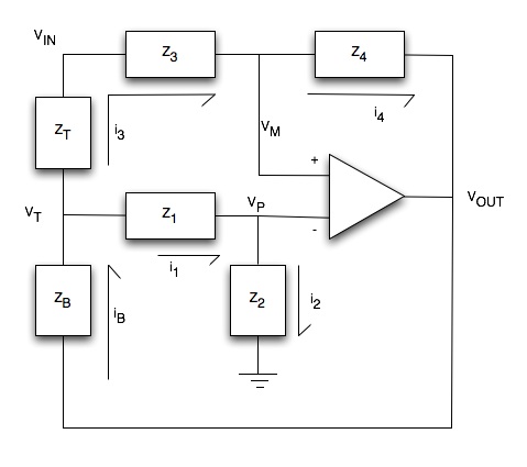
Here's a redrawn schematic with impedances and currents drawn in:

midrange-circuit.jpg


The pot is represented by ZT and ZB:  so if the pot is dialed 'fully up' (maximum boost), then ZB = 0 and ZT = the pot value, etc.

So the three fundamental equations from KCL are:

[list type=decimal]
[*]i3 = i4
[*]i1 = i2
[*]iB = i3 + i1
[/list]

Equation #1 gives us VOUT and VIN in terms of VM:

VM = (VINZ4 - VOUTZ3) / (Z3 + Z4)

Equation #2 gives us VT in terms of VP:

VT = (VP*(Z1 + Z2))/Z2

Equation #3 gives us VOUT and VIN in terms of VP and VT.  I can get rid of the VT term but substituting in equation #2 into equation #3.  The result is:

VP = (VINZ2ZB - VOUTZ2ZT) / (Z1ZB + Z2ZB + Z1ZT + Z2ZT - ZBZT)

So now I have two equations that relate VM and VP strictly as functions of the leg impedances and input and output voltages.  I can now set them equal to each other (standard op-amp ideal analysis) and solve for VOUT/VIN (which should be the overall gain equation).  This yields the following monstrosity:

midrange-transfer2.jpg


So I can simplify by setting Z3 equal to Z4, and dialing the pot fully 'up' by setting ZB equal to zero.  This results in:

VOUT/VIN = 2*(Z2/(Z1 - Z2)) + 1

which looks frighteningly close to Dave's H(s) equation given previously.

If I set ZB = ZT, I get:

VOUT/VIN = 1

Still good.

If I set ZT = 0, then I get:

VOUT/VIN = 2*(Z1/(Z1 + Z2)) - 1

which is just the negative reciprocal of the first equation.  Still good!

So if I substitute in the following for Z1 and Z2:

Z1 = R1 + 1/(s*C1)
Z2 = R2 || 1/(s*C2)

I get:

midrange-solution2.jpg


which matches Dave's solution exactly.

So to sidestep the notions of Q being debated, for this circuit, passband gain and 'bandwidth of the filter' are related....to narrow the filter, C2 must approach the value of C1, but gain drops.  Moving the values for R1 and R2 to increase gain causes the center frequency to shift towards the -3dB points causing bandwidth shifts.  In fact, to have symmetrical response in the pass band R1 must be equal to R2!

Any extremely informative discussion all around!
 
This a very patient demonstration that the interaction between the numerator and denominator's Q is such that taking only one of them in consideration is absurd, although I admit that for narrow BW and high B/C, the analysis of the denominator's Q only gives a good indication of the actual performance.
 
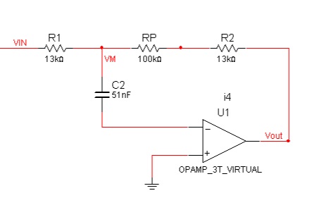
On a (somewhat) related note, if we have the following circuit:

treble-circuit.jpg


Under a classic analysis, there is no current into the inverting terminal, so there can be no voltage drop across the capacitor at any frequency.

Is a good analysis strategy to include a resistance from the inverting terminal to ground (to simulate input bias and provide a DC operating point), and in the equations take the limit as that resistance goes to infinity?

 
Matador said:
On a (somewhat) related note, if we have the following circuit:

treble-circuit.jpg


Under a classic analysis, there is no current into the inverting terminal, so there can be no voltage drop across the capacitor at any frequency.
Classic analysis tells first that the opamp does not operate linearly because it has no DC FB. So it maybe that the current in the cap is null (at least within certain limits), but the output will be unpredictable.
Is a good analysis strategy to include a resistance from the inverting terminal to ground (to simulate input bias and provide a DC operating point), and in the equations take the limit as that resistance goes to infinity?
You may add a very large resistor there, it won't change the fact that the circuit doesn't work. You need to add a resistor from output to neg input; then ther is current in the cap because the neg input becomes avirtual earth.
 

Latest posts

Back
Top