lewilson said:
Check the schematic. The voltages from the cathode to grids are not 0vdc. Maybe some very small coupling caps would work to make a 660 a de-esser. You could have them on a switch
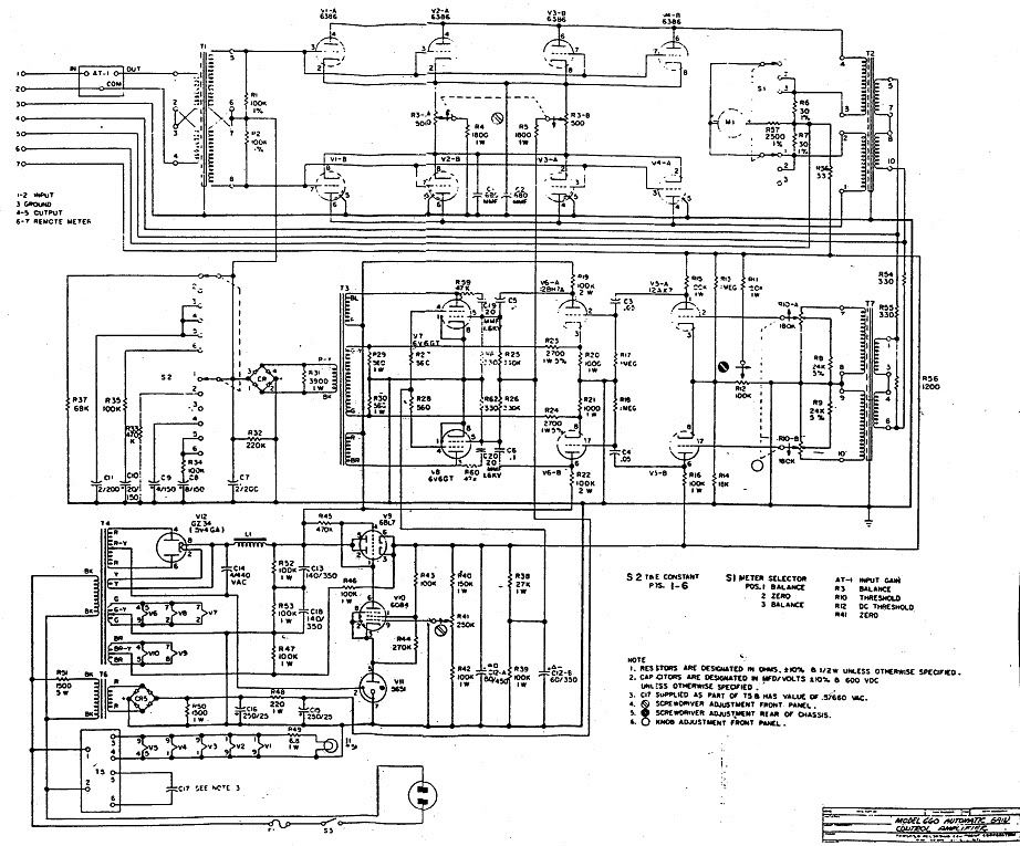
Just to be clear we are talking about proposed modifications to the schematic for this Poor Man's Fairchild 660/670
http://i572.photobucket.com/albums/ss163/rotheu/Fairchild660Mod2.jpg and this timing chain
http://i572.photobucket.com/albums/ss163/rotheu/Fairchild660ModTiming.jpg: not whether you could do this mod with the original Fairchild.
When talking about a DC voltage you have to also have a reference. You can't just say 0V DC.
Let's see if I can convince myself and you in the process.
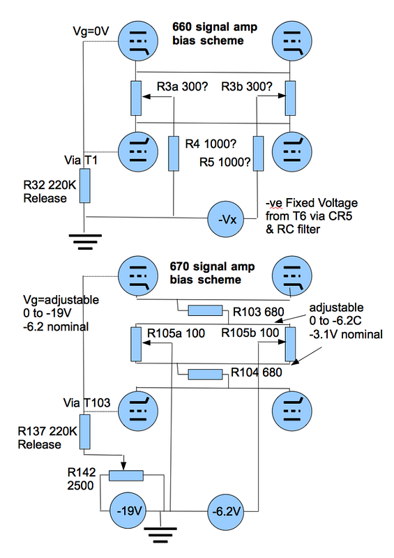
The only DC reference for the grids of the signal chain in Rotheu's circuit is the common voltage of the top of the attack capacitor (to signal ground) and the top of the release resistor, again to signal ground. Otherwise we're talking 10M+ parasitic leakage resistors. When the attack capacitor discharges, the grids should sit around 0V compared to signal ground.
When the unit is initially turned on the valves will see 0V on their grid via the 1M resistor and the release resistor, 0V on their cathode (no plate current), and 100V on their plate, so they'll begin to conduct and try to force around 16mA of plate current to flow (from the 6bc8 curves). If all 8 tubes fed 16mA that would raise the cathode voltage by 8 * 16mA * 100+620+33 ~ 100V meaning the grid to cathode voltage would be -100V, turning off the valve completely, so that isn't going to happen.
The effect of the plate current is to cause cathode current, which in turn develops negative feedback across the tail resistor: effectively a load line of approx 6K (because of 8 tubes forcing plate current through the common tail resistor of 753 ohms).
The effective plate voltage is also 100V (power supply) - the voltage across the cathode resistor = 100 - Ip * 6K but this drop is going to be pretty negligible as a first approx. so the quiescent state should be somewhere near where 6K*Ib crosses the grid voltage versus plate current curve of the 6bc8 with Vplate = 100V
So rather than reaching the full 16mA of plate current, the equilibrium will be reached at somewhere around 0.66mA of plate current = 0.66mA cathode current per tube or a total of around 5mA generating ~4V across the common cathode resistor.
Relative to signal ground the cathode will sit between 0.66mA * 8 * 753 ohms = 4V
Relative to signal ground, the grid will sit at about 0V.
This will maintain a grid to cathode voltage of around -4V (which of course magically corresponds to around .66mA of plate current per tube at Vplate around 100V according hte the 6bc8 curves) thus maintaining the equilibrium.
.... classic self biasing
So the basic point of all of that is to show that the grid voltage in the quiescent state is at 0V relative to signal ground, and so the grid could be safely connected to signal ground in THIS CIRCUIT (not in the original Fairchild) and thus to turn off compression.
strangeandbouncy said:
am really not qualified to answer, and i would hate to be making a chump of myself, but how else is the threshold of compression set? as I understand, no compression will occur 'til the SC voltage exceeds -6.2V.
No?. Otherwise it would compress at ANY level wouldn't it?
So soory if I am wrong!
ANdyP
Again, you have to talk about a voltage and a reference point. The absolute level of the 6.2V and the adjustment of R142/242 has nothing to do with determining the threshold of the Fairchild IMHO. IMHO The side chain rectifier is floating compared to its input signal (due to the inter stage transformer T104/T204) and will switch at the normal ~0.6V of silicon diodes. That voltage is then added to the control voltage by charging C109/C209. The fact that the whole circuit is raised 6.2V relative to signal ground via C215/C215 R142/R242 in the quiescent state is neither here nor there when it comes to determining the threshold of compression (but it does determine DC biasing of the signal amp, so yes you're right in a sense that if the control voltage remains at -6.2V = no charge on C109/C209, then nothing gets compressed, but that is a symptom, not the cause.)
The threshold for DC compression is determined at the input to the side chain amp, not at the output. Have a good look at the biasing arrangement of the 12ax7 of the side chain amp. Draw out just half of one stage, i.e. the upper half of transformer T103, the ac pot R115a, R116 270K, R117 100K pot, 1M R118, V105a (1/2 12AX7) R119 18K & R120 100K. Set the AC pot R115 half way. Turn the DC threshold pot R117 fully left, fully right, and then half way and check/predict what happens for no signal input, and then add on small AC signal.
Is the 12AX7 running in class A, AB, B or is it actually completely under biased in Class C, and only switches on once a significant ac signal arrives?
[
Hint 1. The AC pot has no DC across it. Both sides are at 0V relative to signal earth as the transformer secondary has low impedance at DC. On the other hand, the DC pot has negligible AC across it, as it is connected to the centre tap,
Hint 2. After much crumpling of paper, I came up with grid - cathode bias voltages of -16V, -3.6V & -13V respectively assuming a linear pot and applying Kirchoff's laws.
Hint 3. Check out the 12AX7 data sheet here http://lib.store.yahoo.net/lib/thetubestore/JJ-ECC83-S.pdf and look carefully at the graph of plate current against Ug....
]


")