"Another Poor Man's" Fairchild 660/670

GroupDIY Audio Forum

Help Support GroupDIY Audio Forum:

This site may earn a commission from merchant affiliate links, including eBay, Amazon, and others.
lewilson said:
interesting, I build my 660 from the 670 schematic. I could never find a 660 schematic.
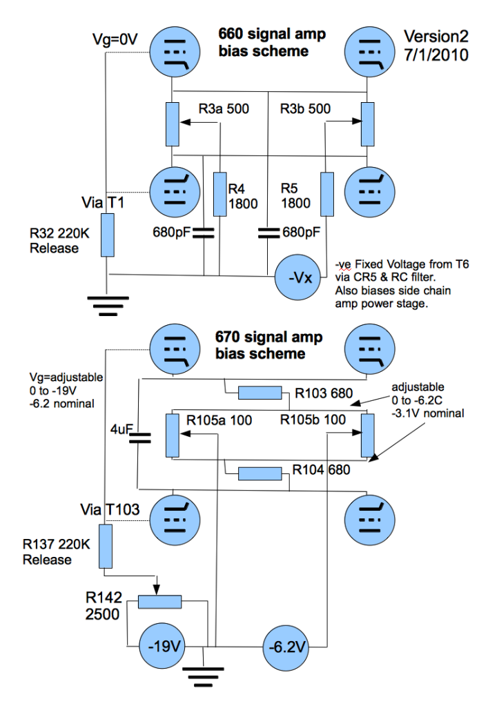
So the grids of the signal amp are not fed a negitive voltage. They are referenced to ground through r32 in parallel with whatever happens to be selected for a time constant.
Cathodes are balanced with a negitive voltage tapped from the fixed bias supply for the output tubes.
Also bypass caps on the signal amp are very small compared to the 4uf that the 670 has.
[UPDATE. I found component values from the Drip electronics manual for their version of a 660 which has a small extract of the original schematic of a 660 covering the signal amp biasing reproduced on page 56 http://dripelectronics.com/documentation/660_manual_part_1.pdf ]
[Update. changed to guess -Vx as 16V after input from Rotheu]

Yes. You are quite correct. And the other thing to note is the position of R104/R105 on the 670 compared to R4 R5 on the 660.

IMHO there is far less "common" long tail in the 670 for signals.

In the 660, the +ve & -ve halves share around 900 ohms of tail (assuming I read the 1800 correctly)
and they have around 125 ohms to themselves from the balance pot (500 set half way in parallel with the other half of the pot assuming I read 500 correctly)

In the 670, the +ve & -ve halves have 680 ohms completely to themselves, whilst the balance pot provides just another ~25 ohms.
But none of it is common to the other half as any current goes straight to the supply.

So the balancing of these two would be pretty different.

And as you correctly point out, the bypass caps are different, but they also bypass different things.

On the 670 it is 4uF in series with 2*(680+25) or around ~ 26 Hz if I'm not mistaken.
Anything above that and the capacitor will dominate.

On the 660 looks to be around 680mmF = old speak for 680pF.
R4 is apparently 1800 and R3 is 500 making 2050 total with 680pF = 105KHz.
Anything below that and the resistors will dominate.

Looks like the bypass caps in the 670 are truly bypass to increase gain at audio frequencies, whereas in the 660 they're only there for high frequency effects.

So they are running quite significantly differently in operation.

Since there never was a stereo version of the 660 (although the link circuit of Rotheu with the diode in the control chain is very clever and would allow stereo linking), it does beg the question of what you want to achieve when building your project. Dual mono 660's, or a 670 with L+R L-r mode, or dual mono 660' s that are linkable (which was not an option on the original)? I personally like the idea of 2 true dual mono 660's (with original 6-position switch-selectable timing chain = "classic" mode) but with a switch to be able to change to the modified timing chain for independent attack and release + the stereo link option = "modern" mode. I mean the cost of the timing chain is peanuts in the whole. That would probably be more useful for me thinking about it further.

I've added the bypass caps on to the diagram and updated the component values.

For the 6v6 (used as the output valve in the 660 side chain amp) you're looking at a grid bias of around -16V on the grid relative to the cathode to stop it melting with Vanode of 300-400V. Since in the 660 side chain, the 6V6 cathodes are connected to ground, that'd make the -Vx fixed voltage around -16V at a guess. In other words (and after some head scratching) Vb = (250+2*1800)/2Ib*4 - 16/2 or Ib should be around 2-3 mA per tube

Any chance of anyone being able to confirm the value of the biasing for the original 660???

660_670_best_guess_biasing_v2.png
 
Any chance of anyone being able to confirm the value of the fixed negative biasing for the original 660???

The filtering caps are rated at 25V, so it's probably somewhere in the range of 14V-18V?

Since there never was a stereo version of the 660 (although the link circuit of Rotheu with the diode in the control chain is very clever and would allow stereo linking), it does beg the question of what you want to achieve when building your project. Dual mono 660's, or a 670 with L+R L-r mode, or dual mono 660' s that are linkable (which was not an option on the original)? I personally like the idea of 2 true dual mono 660's (with original 6-position switch-selectable timing chain = "classic" mode) but with a switch to be able to change to the modified timing chain for independent attack and release + the stereo link option = "modern" mode.

Love the idea, that's exactly what I'm going to do with timing networks! Thanks! ;)

BTW from everything I've read so far in different articles and posts from people who have experience using both original 660 and 670, 660 is by far better sounding unit. There were also a lot of phazing problems related to the L+R, L-R matrix in 670. Dual linkable 660s is the way to go IMO, especially with your "classic" and "modern" modes.
 
rotheu said:
Any chance of anyone being able to confirm the value of the fixed negative biasing for the original 660???

The filtering caps are rated at 25V, so it's probably somewhere in the range of 14V-18V?
There's me making my head ache with maths. grin :)

But aren't those 6v6's (V6 V7 in the side chain amp) going to be running very hard then?  :eek:
 
MeToo2 said:
rotheu said:
Any chance of anyone being able to confirm the value of the fixed negative biasing for the original 660???

The filtering caps are rated at 25V, so it's probably somewhere in the range of 14V-18V?
There's me making my head ache with maths. grin :)

But aren't those 6v6's are going to be running very hard then?  :eek:

I built it with 6AQ5s, which are equivalent of 6V6, with -16V bias they were running just fine.
 
With the 660 running 9db more gain I can see why many people would think it sounds better.
  I wonder if the signal amp as a whole has a few db boost above 1k  or if it was to make the amp flat?
Also, I wonder if the specs for the transformers in the side chain amp are the same as the 670? In particular the input to the side chain? 
Its seems to me that the 660 was designed to accept  a wider range of input signals making it a  bit more usefull for  radio, tv, rec studios, etc.
 
rotheu said:
I built it with 6AQ5s, which are equivalent of 6V6, with -16V bias they were running just fine.
My mistake. Sorry!

I was looking at the curves for the 6v6S from JJ.

6V6S (JJ) G1= -15V will exceed the maximum power curve by some margin (>>100mA) for 400V plate.

Looking at the 6v6GT from other manufacturers, it's much more forgiving.
6V6GT (GE) G1= -15V gets you down to about 60mA for 400V plate
6AQGT (Tung Sol) G1=- 15V also gets you down to about 60mA for 400V plate

Something to be aware of if you're buying tubes for this. Don't go with the JJ 6V6S unless you change the biasing.

I've ordered a pair of JJ ECC99 for this position, so I may increase the 220ohm cathode resistor in the signal amp slightly (390 Ohm and then maybe 330 Ohm) in the modified layout (self biasing side chain amp) at least to start with. Should give a bias point of around -11.5V and 14mA and power of 4W (max dissipation is 5W). We'll see when I get down to building.

lewilson said:
Also, I wonder if the specs for the transformers in the side chain amp are the same as the 670? In particular the input to the side chain?  

According to Sowter, the remake transformers for the 660 and 670 are interchangeable.
http://www.sowter.co.uk/acatalog/SOWTER_TRANSFORMERS_PRO_VINTAGE_TRANSFORMERS_5.html

Read into that what you will compared to a real 660 670. Remember there's a pad before the side chain amp of the 660 & 670, so you can compensate somewhat for the lower gain of the 670 signal amp, although it will obviously be different between the two at max input (0 pad).
 
Yes, I will definitely work but if its the exact ratio im not sure.  They dont make a power supply transformer or b+ choke specific to the 660. At least I have not seem them listed.
 
Also, if you going to build Rotheu's circuit you can use  the Russian 6n5p tube. Its a nice replacement for the 6bc8 . Maybe Rotheu has tried them?
 
lewilson said:
Also, if you going to build Rotheu's circuit you can use  the Russian 6n5p tube. Its a nice replacement for the 6bc8 . Maybe Rotheu has tried them?
I have bought a load of 6K4P-EV Russian tubes (6BA6 equivalent which is used by Manley among others) to replace the 6836's

Planning on using those in triode mode as the curves look similar to 6386, with a very extended cut off down to -30V grid.

That should allow them to behave fairly linearly for amplifying small signals whilst still having a large range of transconductance.
That at least is the theory. Practice may be different. They are also cheap if it all goes wrong. If I get this built I'll be sure to post back.
 
Yes, I know the tube,  I mentioned it on page 6.  I hope the sidechain amp has enough kick to drive them. I think with 4 watts you may get -50 volts. But how quickly?
 
MeToo2 said:
I have bought a load of 6K4P-EV Russian tubes (6BA6 equivalent which is used by Manley among others) to replace the 6836's

Planning on using those in triode mode as the curves look similar to 6386, with a very extended cut off down to -30V grid.

That should allow them to behave fairly linearly for amplifying small signals whilst still having a large range of transconductance.
That at least is the theory.

Hi,
I'm curious, are you planning to replace each 6386 triode with 1 6K4P that has the Plate directly connected to the screen ? Is it that simple ?
 
schlamn said:
MeToo2 said:
I have bought a load of 6K4P-EV Russian tubes (6BA6 equivalent which is used by Manley among others) to replace the 6836's

Planning on using those in triode mode as the curves look similar to 6386, with a very extended cut off down to -30V grid.

That should allow them to behave fairly linearly for amplifying small signals whilst still having a large range of transconductance.
That at least is the theory.

Hi,
I'm curious, are you planning to replace each 6386 triode with 1 6K4P that has the Plate directly connected to the screen ? Is it that simple ?
I'm first going to experiment a bit to be honest. The plan is to use 2 * 6K4P in triode mode to replace 1*6386 dual triode. Yes. The curves look remarkably similar to half a 6386. Theoretically they look better than 6bc8's. And they are so cheap there's no problem if this idea doesn't work and I have to buy another set of tubes. They are literally a dollar or two each. Up until now everything I've done has been on paper which is no substitute for real life experience. To avoid them overloading the screen grid I'm thinking of 3K3 screen grid stoppers (between screen grid and anode) I'm also thinking on adding grid stop resistors (first calculation is 33K) to roll of the response above 20KHz and prevent any oscillation. Then I think I'll have to change the bias scheme to be more like the 660 with an added fixed negative bias to get them to turn off without too much DC current saturating the transformer. But I was thinking on doing that anyway as I'm concerned about the ECC99 running so much quiescent current into the output transformer of the signal chain, so a negative bias supply would be handy. And I was also going to use a 10K:150 ratio on the signal chain amp, as I think I'll be short on current rather than voltage. 125V should still give 20dbm even through an 8:1 transformer (the 660 was apparently 9:1 @ 240V). These are all tweaks to try to optimise for these valves. All of this could change though once I get hold of the real article. First step is to see if I can build a signal amp with the right curves, and then worry about whether the side chain will drive it. Yes I was looking at the voltage ratio of that. The load is very odd (being a rectifier into a capacitor) and I haven't got my head around that fully yet what it will have to look like..... perhaps more like the initial DC charging on a power supply than a linear amplifier, because once the control voltage capacitor is charged there's hardly any load at all on the ecc99. But you have to get it charged in a very short time frame (less than a few cycles at 1KHz), so you need high power but only for a very short time frame and certainly not 5W continuous. Mu changes quite quickly at the start of the curves so it might be fast enough. Then again it might not be. Difficult to predict. Again some experimentation will tell whether this is possible and I promise I will report back. If it works out though it'll be a very cheap alternative. If not I've had some fun, learned something, and not spent a great deal in the process.
 
I decided to try 8 6BA6s instead of 4 6BC8 with the same side chain amp. I didn't change the biasing of the signal amp, everything is the same, just like on the schematic I posted. Plate voltage is 260V (I don't have required zeners for my temporary PSU to adjust it for 240V). Cathodes are at around 24V. Overall current draw for the signal amp is 32mA, around 4mA per tube. The gain is around 10dB and I get some 15dB of gain reduction. The side chain is performing surprisingly well for 6BA6s. I get some very minor thumping when in deep gain reduction, but that's because I have only 10 6BA6s and they are all used, in unknown condition, so I don't have enough to match 8 of them and it's impossible to balance them properly. This simplifies the power supply, you only need 240V reg. and 300V. I played some drums, piano and vocals through it and it sounds really cool. ;)
 
rotheu said:
I decided to try 8 6BA6s instead of 4 6BC8 with the same side chain amp.
Thanks for that. All due respect to your design. You've done this and I'm only starting out.

I think I should start a new thread in the "drawing board" for these experimental ideas with the 6ba6 to avoid confusing anyone implementing your original 6BC8 based design.

Indeed another option I was thinking about was either 6 or 8 6BA6 equivalent on each side, instead of changing the transformer ratio. I have 32 * 6K4P on the way. All from one batch of new old stock. So hopefully I can match a load of them and look at various combinations. Heater current is starting to look enormous for stereo, but it will look physically impressive if nothing else :)

I suspect it is better to reduce the gain slightly of the signal amp output and increase the current drive by changing the transformer. That is more in line with the original 660 (9:1 ratio in and out on the signal amp) The 6BA6 has a much longer cut off than the 6bc8, so having more signal arriving at the input grid shouldn't be a problem (relatively speaking 40V cut off for Vg rather than around 10V & 8:1 instead of 4:1 transformer). I was going to increase the anode voltage too. It's a balancing act, gain versus power versus impedance. We'll see when I try to characterize them. I'm still learning an awful lot.

Yes, the control amp may need more power/voltage to drive the larger control voltage (50V versus 10V) But the expensive bit is the (power) transformers, switches, and case. Not the valves. So having a spare pair of ECC99's ain't a problem for me if I need to uprate those. I can always use them in another project, like a headphone amp. And the 6k4p cost almost nothing.

Re: thump. I don't think variable mu was ever designed for "slam" like a fet compressor. Just imvho.
 
rotheu said:
I decided to try 8 6BA6s instead of 4 6BC8 with the same side chain amp. I didn't change the biasing of the signal amp, everything is the same, just like on the schematic

Hi Rotheu, may I ask if you only directly coupled the Plates and screens of 6ba6's or if you utilised a resistor between them ? I presume the Tbar mod adapter board would be similar and it would be interesting to know the changes implemented there to utilise 6ba6's ?
 
The 6ba6 grid 2 can handle the voltage fine according to the spec sheets. I think around 300 volts. The 6k4p tube is max around 100 volts for grid 2 .You must put a very large resitor in for this tube?  

Someone please correct me if im wrong.  
 
Some data sheets gives 6BA6 screen 2 max voltage 300V, some others 125V... Every data sheets gives some examples with only 100V on screen 2. Safe use in triode mode is with screen2 connected to cathode.
 
lewilson said:
I just finished fairchild 660 clone. I  used the Russian version of the 6ba6 tube, the 6K4P. It is a very nice tube. 

lewilson said:
The 6ba6 grid 2 can handle the voltage fine according to the spec sheets. I think around 300 volts. The 6k4p tube is max around 100 volts for grid 2 You must put a very large resitor in for this tube. 

Hi lewilson, What value did you use ? I assume you put the resistor between the Screen G2 and Plate ?

 
Mine has  been working fine with the grid directly attached to the anode. I use both 6ab6 and 6p4k tubes no problem.
 
This post is about proposed mods to facilitate use of 6ba6/6k4p in the signal amp. There's nothing in here about the existing 6bc8 (real triode) design.
lolo-m said:
Some data sheets gives 6BA6 screen 2 max voltage 300V, some others 125V... Every data sheets gives some examples with only 100V on screen 2. Safe use in triode mode is with screen2 connected to cathode.
Surely (just to clarify) you mean that you should connect grid 3 (suppressor) directly to the cathode?
That would be very normal. I've never heard anyone call anything screen 2 (until now).

lewilson said:
Mine has  been working fine with the grid directly attached to the anode. I use both 6ab6 and 6p4k tubes no problem.

And regarding connecting the anode (plate) directly to the screen grid (grid 2): maybe it's safe in this project because of the cathode resistors and the high load resistance, but I don't think it is generally good practice.

If the anode (plate) voltage goes below 20V on a 6ba6, the majority of the current goes to the screen grid (grid 2) and virtually none to the anode (plate), and so you may end up with too much power on the screen grid (grid 2) because you are only allowed 0.6W on screen grid compared to 3W on the anode. This is common behaviour for (beam) pentodes.

I would have thought because the 6ba6 is really a pentode but trying to act as a triode, you'd need a 3K3 (or even higher) screen grid stopper resistor between the screen grid (grid 2) and the anode (plate) to prevent this? Just for safety when driven into saturation. I've found very little documentation on the selection of screen grid stoppers, but the two theories I have found are to select around 1K or around 1/4 of the load resistance.

For a 6ba6 the screen grid current is approx 1/2 the plate current in normal operations. So Iplate is approx 2*Iscreen grid until you go into saturation (plate <20V). Then the ratio breaks down and there's virtually no plate current for plate <20V. The screen grid stopper resistor causes the screen grid to be pulled down compared to the anode voltage drop, thus providing negative feedback to reduce the current in the screen grid and stopping the tube melting.

This is one of the things I wanted to try in my experimentation. I can find very little documentation about how a 6ba6 / 6K4p behaves in triode mode.

There's a dotted line on the GE graph for "average transfer characteristics" with Ecc2 = 250V and Rc2 = 33K (yes 33K). I presume this is triode mode with a very large screen grid stopper. There's also a "screen rating chart" that is flat going up to about 175v @ 0.6W and then drops off as screen grid voltage increases.

There's just one small graph at the bottom of the 6k4p Russian data sheet and that doesn't go anywhere near grid 1 below -5V (and we'll be operating it nearer -10 to -50V grid1 and max current of around 5mA if we go to 8:1 on the signal amp transformers). It also stops at an anode voltage of 160V.

So it is unclear to me what is causing the limit on the screen grid voltage: too much screen grid current causing excessive power dissipation in the screen grid and fusing, or excessive screen grid voltage causing some breakdown. I'm presuming it's a max power dissipation issue.

Would someone mind making a little drawing to clarify what is "safe" triode mode according to you?


Here's my straw man. Seems to me changing the ratio of the signal transformer to 10K:150 is the easy way out and staying at 4 6ba6/ 6k4p tubes per side, rather than juggling with the number of tubes to reduce current per tube, or pushing Vscreengrid up to get the required power. The ratio of 10K:150 = 1+1:4.08+4.08 is closer to the original 660 signal transformer ratio of 1+1:9+9. Why did I go for this value? Well Edcor also make one in the same series as the 10K:600 also for ~$13.

You can use Vplate =125V into 40K load and bias at 4mA giving total power <0.6W per tube total (not just the screen grid) and you can still probably get +27dBm out (same as 660) at clipping. Since the screen grid can cope with 0.6W on its own that's inherently safe. That's also within the power rating of the transformer (4*0.6W) although it wasn't truly designed for 600 ohm working. Complicates the power supply again a bit in that you need 125V regulated. But I guess you can derive 125 from a 240 regulated supply.

That'd suggest at a first approximation of screen grid stoppers of around 2K2 - 10K in order to be safe of a near short circuit load on the output if someone accidentally loads the output too much and simultaneously forces it into clipping... (drop Vscreen grid by 20V drop from Vplate of 20/10mA => roughly 10K max or 2k2 min. I'll see better during measurements. For normal operation (no clipping) the plate current for ~8mA screen grid is around 16mA (if it flows) so power plate = 16mA*200Vmax /2 = 1.6W = also well in spec. The ac voltage drop across a 10K screen grid stopper for a 40K load would only be less than 10% of the drop across the nominal load (as Iload = Iplate+Iscreen_grid = 3* Iscreen_grid) For 2k2 even less. Although of course I can't predict to exactly what is going to happen without measuring because of the complex and non-linear interaction with the plate current around clipping. It'll probably need some slight juggling, but it should be about the right ballpark for a first go.

660_670_safe_triode.png


Or am I missing something? Almost certainly!
 

Latest posts

Back
Top