You are using an out of date browser. It may not display this or other websites correctly.
You should upgrade or use an alternative browser.
You should upgrade or use an alternative browser.
API 312 Thread!
- Thread starter fallout
- Start date


Help Support GroupDIY Audio Forum:
This site may earn a commission from merchant affiliate
links, including eBay, Amazon, and others.
JLM Audio
Well-known member
The 5 rail JLM Power station Power supply kit will run 8 x Fabio kits easy as long as the regulators are bolted to a good heatsink or metal case as they can handle 1.5A each with the right amount of heatsinking. The relays are the same as the ones we use on our 99v kits. If all the 5v relays were on at once they would draw 900mA Max which is going to work but make the 5v regulator run hot so it will need the most heatsinking etc.
If you don't have the relays yet it would be wise to buy 12v or 24v ones as they draw less current each and because they run on a higher voltage the regulator does not run so hot. So if you fitted 12v relays the current would drop from 900mA to 375mA Max. If you fitted 24v the current would be 270mA Max which is even better and the regulator would run even cooler. All that is needed is to adjust the voltage with the trim pot to 5v or 12v or 24v with the right relays fitted and change the resistors in series with any LED's to 1k for 12v or 2.2k for 24v on Fabio's PCB. Also make sure CSW1 cap on Fabio PCB is high enough voltage.
http://www.jlmaudio.com/JLM Power Supply.htm
We have these relays in 5v, 12v and 24v types for $3.50AUD which is about $2.80USD each. Air Mail for these relays is about $6USD.
Joe
www.jlmaudio.com
JLM Audio
Well-known member
Hi Pedro
Looking at Fabio's circuit the relays look like they default to mic in, no pad, no phase reverse & Mic transformer output so should work without connecting 5v power to the relays. So you do not need to bypass anything. Just don't connect the 5v rail to the PCB. or if the 7805 is blown on the power supply just remove it and you should be up and going.
Joe
www.jlmaudio.com
robomatique
Well-known member
What about swapping the 7805 to a 78S05, that should be able to handle 2A. Or is it simply a heat question, maybe bolting to chassis would solve the problem?
Robert
Robert
alo
robert,i think it is a question of heat,more than amp rating.
one more doubt.i used cinemag 75101apc.do i have to make any special coccection,other than stuck the tranny in the board and solder it?.
best regards
pedro
robert,i think it is a question of heat,more than amp rating.
one more doubt.i used cinemag 75101apc.do i have to make any special coccection,other than stuck the tranny in the board and solder it?.
best regards
pedro
Yea Rob, good idea!
Pedro, you need to solder the pins 1&2, 3&4 for 150 ohm operation, as indicated in silkscreen. Just thow in more solder into the pad and they join. I can take a pic if you get in doubt.
:guinness:
Fabio
Pedro, you need to solder the pins 1&2, 3&4 for 150 ohm operation, as indicated in silkscreen. Just thow in more solder into the pad and they join. I can take a pic if you get in doubt.
:guinness:
Fabio
pmroz
Well-known member
.
Fabio, if not using relays, i need another switch for DRL_HZ, correct?
So counting mic/line switch, that's 5 switches per channel?
Don't see 'NOTE 3' anywhere. only NOTE 1.
If i use relay here, it auto-switches when plug is in?
If so, maybe this is the only relay i'll use.
BTW i like all these input options.
Fabio, if not using relays, i need another switch for DRL_HZ, correct?
yep
")
So counting mic/line switch, that's 5 switches per channel?
Right! phantom, mic/line, di, pad, flip.
Don't see 'NOTE 3' anywhere. only NOTE 1.
oops, will check this out.
If i use relay here, it auto-switches when plug is in?
If so, maybe this is the only relay i'll use.
Right on.
I's say use at least this one. It's very interesting to have this feature of auto-DI.
:guinness:
pmroz
Well-known member
Fabio, yes, that is cool. i like that you put that feature in.
I'm going to jumper DRL_HZ (IC sockets are in relay spots now) until relays get here. Any problem?
Another Q... when not using the relays PAD and POL, it seemed right to mount the (PB) switches' with bottom pins as normal, then jumper off the top leads to relay spots. That way the LEDs get switched on. Correct?
If not i'll try 7824 for 7805, 24v relays in all spots, and change LED Rs
pmroz
Well-known member
.
man i am so dumb.
Don't want to chop up Fabio's nice traces
Too dumb for next plan.
Which is try to make the 4 pre / 1 PS config work:
Aromat TQ2-12V on all relay spots (11ma instead of 28)
The 12V version of this reg instead of 7805:
http://www.national.com/ds/LM/LM1085.pdf (Digi #LM1085IT-12-ND)
... 3a rating (or 5a version LM1084)
No need for R10
Adj RLEDs to taste.
toroid is 50va.
should be well under 1a on soon-to-be 12V rail with everything on...
...any comments would be great. Relays aren't cheap, i'd hate to figure it wrong the first time (like some other stuff i've ordered).
But i'd like to go for it.
Paul
alo
damn,it works,but not at all okay.
with the pot fully counterclockwise,there is sound,and fully clock wise,the amount of sound it is the same.
the pot i am talking about,it is 22k rev log dual.it has two rows of pins.
i just connected one row,which i think it is the right way.
now what?.
best regards
pedro
pmroz
Well-known member
.
.... 1085 pinout is different...in/out/gnd. But even LM7812 (LM340T-12) at 1a, 1.5max should work (same pinout)...
...with 12v relays, everything on at once, 4 channels i get 700ma. (max 176ma relays, 160ma opamps, 360ma LEDs, did i miss?)
guess i'm more worried about neglecting any other current draws in calcs, and if i might fry something with 12v.
Doesn't appear so but i've missed many things already.
If it 'should' work, i'll try it, we can find out...
ps can't find 78S05 ? Is there 78S12?
alo
damn it works.
now time to end those 2520bc rev1.
just need to think about the psu for 4 channels.
note/i used sowter clones in output,and cinemag75101apc in the input.
now,i need to figure out what i am gonna do next,besides finnish my new record.
best regards
pedro
damn it works.
now time to end those 2520bc rev1.
just need to think about the psu for 4 channels.
note/i used sowter clones in output,and cinemag75101apc in the input.
now,i need to figure out what i am gonna do next,besides finnish my new record.
best regards
pedro
Hello!
Some reports from the just finished APIs!
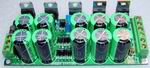
Got 8 channels finished, 4 channels per 1U rack. I ended up connection the SW regulator to R1/C1, the 7805 heats a little but with a good heatsink, it works ok.
They were send to the studio so we can play with it a little next week
The 3 Forssell 992 channels (with JT16-B, CMMI-10B and CMMI-5C) sounds so good also. Never heard a servo circuit in action so this week will be interesting.
Also one channel with an 1:7 input transformer prototype...
Got some API.25.20 from Greg B. (thanks a lot man!) to compare with the 2.5.2.0.BC, will run into RMAA also and report back to you!
now time to get some sleep... more later
OH BTW SOME IMPORTANT THING:
don´t use 82k for R3 and R4 in the 25.20BC... it oscillates at hi gain
cheers!
Fabio
Some reports from the just finished APIs!
Got 8 channels finished, 4 channels per 1U rack. I ended up connection the SW regulator to R1/C1, the 7805 heats a little but with a good heatsink, it works ok.
They were send to the studio so we can play with it a little next week
The 3 Forssell 992 channels (with JT16-B, CMMI-10B and CMMI-5C) sounds so good also. Never heard a servo circuit in action so this week will be interesting.
Also one channel with an 1:7 input transformer prototype...
Got some API.25.20 from Greg B. (thanks a lot man!) to compare with the 2.5.2.0.BC, will run into RMAA also and report back to you!
now time to get some sleep... more later
OH BTW SOME IMPORTANT THING:
don´t use 82k for R3 and R4 in the 25.20BC... it oscillates at hi gain
cheers!
Fabio
fallout
Well-known member
[quote author="Bauman"]
OH BTW SOME IMPORTANT THING:
don´t use 82k for R3 and R4 in the 25.20BC... it oscillates at hi gain
[/quote]
So what values should be used for R3 and R4? Thanks!
-Jay
OH BTW SOME IMPORTANT THING:
don´t use 82k for R3 and R4 in the 25.20BC... it oscillates at hi gain
[/quote]
So what values should be used for R3 and R4? Thanks!
-Jay
So what values should be used for R3 and R4? Thanks!
20K seems to work ok til now.
:guinness:
Fabio
pmroz
Well-known member
.
Fabio, thanks for that update. Glad to hear your 4ch with 5v supply is working.
On BC, is it correct that if R3 = 20k, sum of R4 + R5 should equal 20k?
BTW, based on the last posts, i got TQ2-12V and L78S12CV.
L78S12CV = same pinout, 2a 35V max, so hooked to R1/C1 like yours.
Tracking all week, try to test 4ch next weekend.
Great news Paul!
Yes, exactly.
Hope to track so drums this week!
cheers!
Fabio
On BC, is it correct that if R3 = 20k, sum of R4 + R5 should equal 20k?
Yes, exactly.
Hope to track so drums this week!
cheers!
Fabio