


Hi js.joaquins said:Fastest options, diode clipping, very efficient to limit peaks, RMS another story. Another option is to limit the rails of the amp and add a resistor at the output so certain max power could be delivered from the amp to the HP.
If you want a real limiter you may go for a FET or any other simple topology, Fet being the option 1, diode bridge and transconductance after I guess.
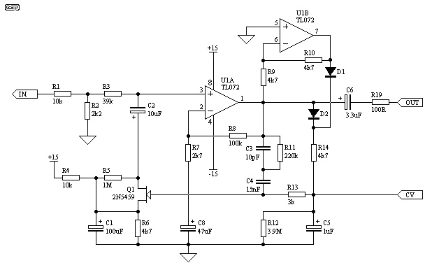
For FET:
1 Fet per channel, some caps and resistors for polarization and an opamp with a couple of diodes for control voltage.
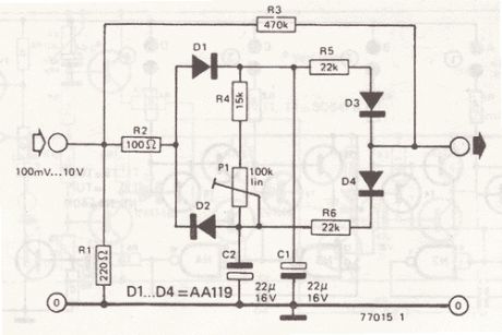
For diode bridge:
4 diodes per channel, one resistor, same for CV.
A passive diode, nasty but working (tried out by myself, it could add attack release, ratio and even do asymmetrical compression)
For transconductance:
3 transistors per channel, some resistors, same CV.

A CA3080 or LM13700 also use this topology but already solved in an IC.
Times could be fixed for fast attack and release for taste.
/*images are for reference of the topology, not the final design that you should use, just to explain my self better, as amp you probably could use the one you already have 2nd and 4th scheme doesn't have the CV generator (rectifier and time constants)*/
JS
How to add attack and release for the passive diode design ?
Thanks


![Soldering Iron Kit, 120W LED Digital Advanced Solder Iron Soldering Gun kit, 110V Welding Tools, Smart Temperature Control [356℉-932℉], Extra 5pcs Tips, Auto Sleep, Temp Calibration, Orange](https://m.media-amazon.com/images/I/51sFKu9SdeL._SL500_.jpg)


