Bo Hansen DI layout

GroupDIY Audio Forum

Help Support GroupDIY Audio Forum:

This site may earn a commission from merchant affiliate links, including eBay, Amazon, and others.
Silent:Arts & Bo,

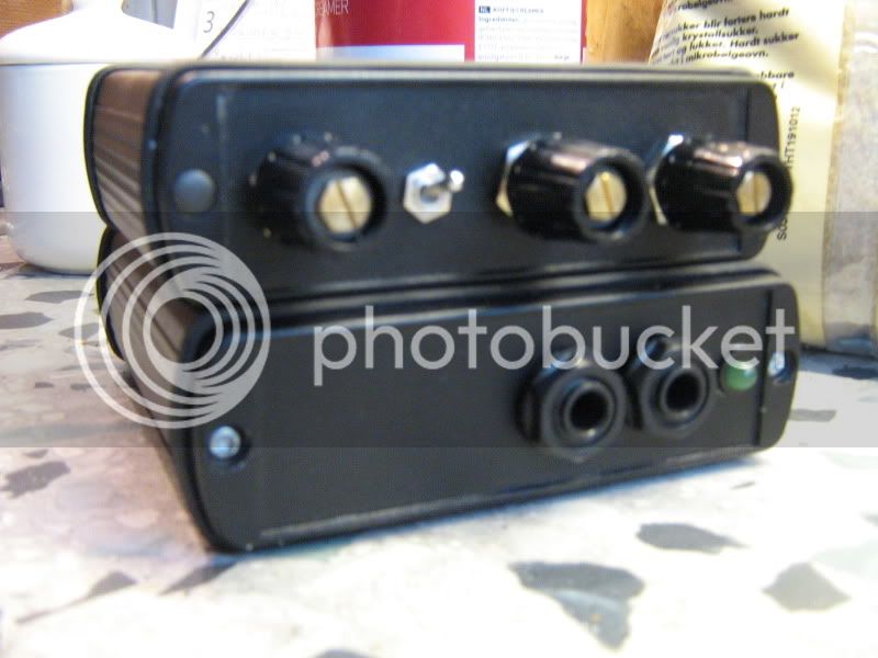
Hello, I actually decided to build another DI Box because this project was very easy to do and was a lot of fun for me, being a beginner to all of this.  Silent: Arts, I remembered your advice on the proper connection of the Cliff plastic jacks on this new project and obviously your advice was terrific and worked beautifully.  I just have two more questions for you and Bo about (DI Box's in general) and another possible mod. 

The first question is about the amp output jack: Is this a "Bypass out" whereby my bass/guitar(s) signal will still remain a high Z impedance, or will the circuitry change it to low Z?

The other question is:  Can a tube be used in this circuit, or has anyone here on the forum attempted this successfully?  I'm asking this because a friend of mine has all tube gear in his studio and most of his equipment is high-end vintage stuff that he's has since the 1970's and he's quite partial to tube-only gear. 

That's all for now guys.  Thanks for the help and support for this project!  It has been a lot of fun! 

Regards.

Jon Slaten 
 
Im not an expert by any means, but I believe with a small amount of math to find new values, an external power supply, and a significantly higher Vcc (B+) you could rework the circuit as a valve box... But why bother, really? It'll probably be more work than starting from scratch, and it's a very nice sounding DI as is (I have 2 with the Haufe transformers)!

You could build one of the Alembic F2B valve preamps with the same backwards 1:5 mic trafo on the o/p  for a valve solution... There was even a version posted here at one point with negative feedback to reduce distortion and gain... Probably be work out better! I have plans to do this soon, with variable feedback...

Mo
 
I have been searching for the Thomas Holly thread with the phantom powered tube DI using a DC to DC converter for the heater. 
Anyone remember the thread name?  I have not seen a Thomas Holly post for some time.
 
Jon,
A tube DI would be a totally different build, you can look for "tube DI" or "tube direct box" , there are quite a few ideas arround there.

regarding your other question, the output jack is not what you call "bypass out" as implemented in some other DIs. it's taken from output of the second transistor, with its fixed output impedance, wich is higher than the balanced output Z, but can't behave exactly the same as a passive guitare pickup coupled straight with the first tube stage of your fav guitar amp.
by the way, you probably can implement such a "bypass out" simply by adding another femal jack in parallel with the input jack. perhapps some resistor values migt be tweeked, I think I remember I have seen this discussed somewhere in this topic...
Laurent.
 
Yeah I know, I figured that.  I had to just put that out there and see what you guys thought.  I'm a complete novice, so I couldn't do something like that unless it was made available on a vero board.  With the two DI's I completed recently, instead of trying to iron the copied traces to a copper board, I just installed the components on a perfboard and copied the traces exactly by looking at the silkscreen and just slowly ran the .020" tinned wire out exactly like the PCB and soldered it all up. It works perfectly and all DMM checks measured within +- .5 volts.  So I did something right there.  Oh well, hopefully there is a somewhat "simple" tube DI out there somewhere.  Thanks for the advice guys.

Jon Slaten
 
Pyjamen,

I read through your post several times on what you mentioned about the output jack.  I apologize here because I am trying my best to learn all of the language of electronics, but would you mind saying that again differently.  As you would say to a 6 year old child.  You mentioned this:

"It's taken from output of the second transistor, with its fixed output impedance, wich is higher than the balanced output Z, but can't behave exactly the same as a passive guitare pickup coupled straight with the first tube stage of your fav guitar amp."

Ok Pyjamen, so the signal comes from the 2nd transistor, and this transistor has a "fixed" impedance.  And you mentioned that this impedance is "higher/more than the balanced output Z (the XLR cable).  So are you also saying that it DOES behave the same as a passive guitar pickup?  That means it's HI Z correct, but with more gain?
 
Slaten,

The "amp output jack" as Pyaman say, is a un-balansed output after the amplifier but before the output transformer.
The impedance is a lot lower compare with a passive guitar, so it can drive a long guitar cable with out any problem, and it will not disturb the instrument because it is not connected in paralell with the input jack.

As also mentioned previously,

Replacing the transistors with tubes, is not so practical, reason is that the tubes are working at higher voltages, and also need heating that draws high current.
This is complex to get out of the phantom power from the microphone input.

There are ways to overcome this problem, as Gus was talking about, you can used a "voltage converter" and miniature tubes that use less heater current, or using high frequencey to generate heat for the tube.

But the circuit is totally different, so it is pointless to use my design or circuit board for the same.

It is better to build a circuit with a normal tube cathode follower and run this with a power supply that is connected to the mains outlet.

--Bo
 
Bo

Thank you for the reply and thoughtful information about your work.  I read about DI boxes on the internet about 3 months ago and realized how important having one in my studio would really benefit me.  I was curious about the "DI Box" and by coincidence, read a post on a forum somewhere and a guy was writing about your box and how great it sounded!  From that moment on, I was on the internet searching for your DI box and how to build one for myself.  I still can't understand how you designed this project and using your knowledge and experience you just created this from an idea you had one day.  I am saying this because I don't know much about electronics and have just recently started to learn about it.  So I will tell my friend that I could build a tube di box in the distant future.  I made 2 of your DI's and that is all I need for recording my Mexican Fender PBass and maybe the Les Paul as a DI and mic'ing it through my cabinet.  I will pass on your information to my friend. Thank you answering my question about the amp output.

Jon Slaten
 
Jon,

"I still can't understand how you designed this project and using your knowledge and experience you just created this from an idea you had one day"

This design is not "rocket science" it is a very simple basic design, yet perfect for this purpose. (you can read more about it here: www.hansenaudio.se/techpage.htm )


I had work as amplifier designer for 10 years when I did this design, so it was no problem for me.

The idea for it came when I, as a recording engineer had trouble getting a good bass sound.
At this time in Swedish studios, there were mostly self-built passive DI-boxes with very small high ratio mic transformers, and this had poor headroom in the bass and sounded pretty muddy.

--Bo
 
The last couple of weeks I had been busy with a bit of home improvement : redo the plasterceilings, added a lot of insulation, new paintjobs, etc.

At last, today I had the opportunity to do :..... Nothing !

So, I built a few boxes for my guitar !
Rossi Re-amper, and a Hansen DI.

I got the boxes from work, they were thrown away, so I grabbed them from the dustbin.  ( I'm all about recycling baby, yeah !  ;D ) I need to have another front for the DI though, that's why the jack entries are so close to eachother. I also have to get a few nice knobs for the pots, what I used is just what I had laying around. Yes, the caps are missing...

Anyway, it just took me 3 hours to build these 2 boxes, including drilling, soldering, wiring. great !
I haven't tested them yet, because my mixing console is down for a week or 2, but there's not much that can be done wrong, right ?

That's a good way to spend your time, right ?
HansenRossifront.jpg


And the insides and backviews can be seen here :
http://s71.photobucket.com/albums/i126/helterbelter/Rossi%20Hansen%20boxes/?albumview=slideshow
 
Ok I have two questions  :)

I accidentally short pin 1 to pin 3 (for les than a second fwiw) while phantom was on. Is there any chance I destroyed something in my circuit? It seems like it operates normaly but is there anything I should double check (like a cap for example)?

Also, I read that Bo suggests to connect the XLR tab to pin1 and then to the same screw I use for the 'chassis' connection, which is one of the XLR screw in my case. Is this not already done in the PCB? I can see a trace from 'chassis' to pin1 on the PCB.
Also, in Bo's photo the tag is unsoldered from what I can see http://www.hansenaudio.se/big%20box%20inside.JPG

The DI looks to work OK but I'm not sure about grounding/noise issues. I even feel some electricity in my fingers sometimes when I touch the strings. Not sure whether is the DI or the crap lines in my house (I feel the same when I'm touching my macbook pro).
I'll take another DI from the studio to check how it behaves at home. Hopefully I'll figure out if it' the DI or not...

thanks
Michael
 
helterbelter said:
I haven't tested them yet, because my mixing console is down for a week or 2, but there's not much that can be done wrong, right ?

That's a good way to spend your time, right ?

Yes sir!I have built two of the DIs also-with those Haufe-transformers!Believe me:They are awesome!!!
Have checked them in the studio and compared to some others I had arround here,and that means against some expensive types too.What can I say-I think i will never touch the old ones again ;)
Have done a ReAmper (Rossi) within 90 minutes or so-a great sound-tool too!

Have fun,

Udo.
 
Michael,

As I said in my building description:

The metal case/housing for the DI-box electronics, shall only be grounded on the XLR output connector pin 1, and also connected to a solder tag fixed in one of the XLR fasten screws.
(this is the only ground connection to the metal case)


It is the solder tag/lug sitting on one of the two mounting screws for the XLR connector that shall be the only box grounding point  for both the XLR pin 1 and the cable that goes to pc-card "chassis conecting point"

I dont talk about the extra ground lug on the XLR connector, but you can also use this together with the other external solder tag/lug if you want.

About that you accidentally short pin 1 to pin 3.
There is no chance that you have damaged or destroyed electronics in the DI-box, so you need not worry.

--Bo

 
Hi Bo & Everybody,

Excellent project, I need some DIs so I will give it a try!
Wowi, nice tip, saves some metalwork too ;)
Ordered from Thomann, even cheap including freight to Norway!

Silent:Arts, how did you make that finish? Looks really good, sort of marble-ish (if thats a word..?)

Cheers everyone
Rune

 
Hey guys. I just have a quick question about the OEM Tranny. I have an extra one still in the box. I want to build a passive DI so I can use it backwards to try some reamping with it. The input impedance is 6k and output is 150 ohms. Thats only 40:1, but recommended numbers 500:1 with an input impedance of 50k and 100 ohm output. What do you guys think? Would the OEM tranny be fine?

Jon S
 
Hi Slaten,

You have probably miscalculated the turns ratio.

You say OEM transforms but you might mean the OEPA262A3E, which is available as an alternative to my DI box.
This OEP has a ratio of 1:6,45 / 150 ohms to 6.25 Kohm, with parallel primary and secondary used in my DI box.

Possibly can it fit as passive DI box if you have the secondary connected in series, then you get the input impedance around 25 Kohm, but this load down a passive guitar a lot, but can work well on a synthziser or similar.

A transformer suitable for passive DI box usually have a ratio around 1:10 and 1:20, (used backwards) this was a common ratio for the microphone transformers used to for old tube gears.

--Bo
 
here's mine.
thanks to silent:arts for the quick supply of the pcb, haufe tranny.
i originally wanted to use a cheap thomann DI as a housing as suggested by volker but i ended up with the B-sized casing...i just love these boxes for their size and feel.

EDIT: i just read the entire thread and i'll definitely change the jacks to isolated ones for use with an amp and effects.
Bo is awesome. thanks so much for this extremely good sounding D.I..i'll built two more of these workhorses.

IMG_0327.JPG

IMG_0328.jpg

IMG_0330.jpg

IMG_0331.JPG
 
I built a cheapskate version using the same enclosure, I used it for a reamp too a while ago. I didn't use OEPA262A3E transformer, I took a chance on this one Z21808E (1:6), because I was curious about it. Not much information but there is a datasheet:
http://docs-europe.electrocomponents.com/webdocs/0d72/0900766b80d72828.pdf which seems to suggest better(different at least), frequency response than the A262A3E. From what I can tell its; 150 primary/5k secondary but I'm not sure exactly.
I had to use 2x 47ohm 5% resistors for the 100R hopefully thats not going to make too much difference!?
I was surprised that it worked with no major hiccups. It needs roughly 30db of mic pre gain to get a good level, does that sound right?
Much thanks to Bo, the information here in the thread and at hansenaudio has been a great help.
Matt
 

Attachments

  • BoDI.jpg
    BoDI.jpg
    385.7 KB · Views: 175

Latest posts

Back
Top