Bo Hansen DI layout

GroupDIY Audio Forum

Help Support GroupDIY Audio Forum:

This site may earn a commission from merchant affiliate links, including eBay, Amazon, and others.
complete.jpg


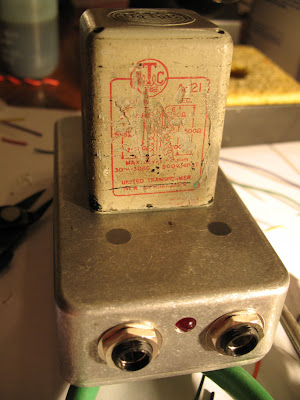
Just finished another - my other has an OEP xfmr, this one a UTC A-21 that has been getting dusty. I know the impedance match is not "to design", but I figured I'd build it and find out if it works (well). It does.

Compared to the OEP, this one is darker - I kinda like it better, but I'm into old thuddy bass sounds.

Reused an enclosure, filling the holes with JBWeld.

Thanks again Bo!

Here's some more pics:

http://lh6.ggpht.com/_EHQRT0x3gro/TON1gj7c0ZI/AAAAAAAAANc/wxIUjWkrQG4/box_xfmr.jpg
http://lh4.ggpht.com/_EHQRT0x3gro/TON1gd-Tr0I/AAAAAAAAANY/6FC-Z64Sl-k/box_pcb.jpg
http://lh5.ggpht.com/_EHQRT0x3gro/TON1gn6XpLI/AAAAAAAAANg/bVHey1Jmknc/done_pre_install.jpg
http://lh4.ggpht.com/_EHQRT0x3gro/TON1g5CZDaI/AAAAAAAAANk/KsMSW0vsA-c/complete.jpg
 
Mine works very nicely too. Thanks for the project.

Anyway, good to see all of this DIY going one! Nice work with that UTC - looks 'old skool'!

 
Sverige_cruz,

UTC A-21 a very good transformer, but to low impedance on one side to fit this application.
500/600 ohms is a lot to low for the DI-electronics to drive.

Unfortunately there is no suitable transformer in the UTC input series, the closest is the A-39 (Scully 280 mike transformer) configured in 2000 ohms to 150 ohms, but even this have a bit to low impedance on the "Hi-Z side".

There are two UTC inter-stage transformer that might be usable.
A-34 configured 6250 to 125 ohms or 500 ohms.
A-44 configured 4000 ohms to 150 ohms.
These are large transformers that will be good for 1 watt output.
Perhaps it might be worth a try for experimental purposes.

--Bo
 
Greetings to all.

I got to say that i was lurking (well, a lot) around here ... but it's time to post.

I don't know of a better place to ask what i want to know, and i also feel i got to share something after all i read here. Well, to start participating at least.

It's not a thread hijack - what i have is four transormers, that i got from a guy here and am speculating of using them for this DI project. I suspect the guy scavenged them out of some mixer, but he couldn't (wouldn't?) tell anything... All i get of them is (almost unreadable) print saying "ET(?) 3603" - that would be my guess, it's pretty much unrecognisable. Also they seem work fine as a passive line to mic - i guess something of a 5:1 rather than a 10:1, but i haven't put them through any kind of test to be sure. I've  just fed line signals (keyboards, aux busses) to mic inputs through them, and they seem to cope fine, with some gain loss ...

Anyone can propose a quick test for me that doesn't include precise signal generator to actually get some numbers about them?
I suppose this is THE place to find guys who know about trafos - so, gentlemen can anyone recognise the suspect?
Thanks a lot.

And thanks for this DI project. I'll be doing this with or without these transormers...
cheers


Attachments

  • front.jpg
    front.jpg
    35.7 KB · Views: 46
Got a side view, also. Phone's there for size reference, but i don't know if  it really helps ...
 

Attachments

  • side.jpg
    side.jpg
    38.2 KB · Views: 37
Of course, i don't want to be rude. If anyone thinks this question sould have it's own thread just say ... thanks
 
Thanks.
Yes, that's also what i thought - big chance it's a sowter. I went through those lists of their old trafos, but no luck. I just don't have enough data ... these numbers are just not readable enough and when i assume the mark is 3603 that gets me to a sowter which was a 600 ohm 1:1. And this one definetly isnt 1:1. It definetly brings signal down (didn't wire it up in reverse). Very likely this one's a mic input - 1k or 2k primary, 200ohms secondary, but i'm going to check that more precisely  when i get a signal generator.

Could this one be an OEP? I can't find any reference for older OEP products...
 
You could apply a sig gen output of 1V peak-peak or so at a useful frequency, say 1KHz and
measure the output voltage on an oscilloscope (could be a PC based or a standalone one).

That will give the turns ratio.

Use a multimeter to determine which pins have coils between them by applying
the continuity checker very briefly.

Measure the dc resistance of the coils, again by applying the multimeter resistance checker
briefly (so as to reduce the risk of magnetising the transformer core and thereby increasing likelyhood of core saturation)

Multiply the dc resistance by 10 for a rough estimate of the coil impedance.

That's the simple and crude way to characterise the traffo.
 
Hey alexc, thanks for the tips!

i got this with my DMM, on the first trafo of the four:

- one coil measures 1325, the other 37;  times ten, is it what it looks? a primary of 10k? how sure can i be? i get it it's a rough measurement, but it gets me the region, right?
near (well...) 200 on the secondary. 

i still have to get a signal gen. and check the other three to get a green light use them in this project.

silent:arts - those are great looking boxes!

cheers to all.

 
Here are my two recently finished workhorses! with OEP transformers
They are a bit shabby chic as my wife calls them. :D dont know if that translates
I tried to do the iron on tranfer method for the printing. It turned out to work quite well on the aluminium case. I just wasnt patient enough. But I quite liked the vintage feel of the print so I didnt bother to redo it.

Henrik

IMG_0311.jpg


IMG_0312.jpg


Bo Hansen said:
Ipkyer,

Great to hear, 22 pieces of my DI-boxes, I am honored that you did this as a soldering project at college.
It would be fun to see a group picture of all these.

--Bo

I wish I had taken one at the time (picture), I'll post pictures of some of the finished ones soon though :)
 
Hey everyone, I finally finished two of these.  They sound great!  Thanks to Soren and Luny for the layout, and of course to Bo.  : )


http://lh4.ggpht.com/_ytgJgDa8utQ/TSIwE0e-yBI/AAAAAAAADKA/q6mEPknjlow/s576/Bo%20Hansen%20DI.JPG
http://lh4.ggpht.com/_ytgJgDa8utQ/TSIwFtVTXcI/AAAAAAAADKE/WYp2kXjONs4/s800/Guts.JPG

 
Gemini,

I think this type have very low ratio around 1:1,5, so in this case, it is not usable for my DI-box.

Beyer have some other types that you can try to find:
TR/BV 3.51.0.05.0300
TR/BV 3.52.0.05.0300
TR145/BV35799
TR45/BV35536

Or a other German brand MB/Mikrofonbau (MB-Electronic Gmbh) type 4481

All types have a ratio of 1:5 and fits in my DI box if they are used backwards.
The downside may be that they are quite small and have not very good headroom in the low end.

--Bo
 
This was my first ever DIY project and have recently just got into electronics.  I completed the project earlier this evening using an OEP AE262A3A tranny and pulled out the DMM to check some final readings.
 
I plugged the DI box into my Presonus M80 and got the red LED to light up on the DI box and plugged my bass into the input.  I got nothing on the channel output level even with gain pegged right!? I used a DDM and took all readings as per Bo's tech page and got 23.6 volts on the positive side of the LED, and then measured 10.96 volts at the junction of the 10uf cap, 3.9k resistor and the emitter lead of the 560C.  So all measurements good. 

What could be the problem?  I used a Cliff UK plastic PC jack that has 4 poles that I pulled off of my old 4 track's  board.  I soldered the + wire to one of the 2 back poles and the other to a front pole.  I dunno, maybe my jack is bad?  Anyone have an explanation?  I'm stumped.  I also check all traces for solder bridges and everything checked out.  Is there anyway to check for voltage going into the board from the bass when I hit a string?  Thanks

Jon


connect the two front pins and the two back pins of your jack together.
4 poles means normalized / switching.
you might use the switched part at the moment, which isn't connected to the plug if inserted.
 
Silent:Arts,

Thanks for the reply.  What I did earlier before logging back on here, was just removing the jack and installing a new one from an old Boss effects pedal I never use anymore. Whatever the problem was earlier, was solved with the new jack. Anyway, Bo's DI sounds really good and this was a really fun project.  Bo, thanks a lot for giving us a new tool to make our music sound better.

Jon 
 

Latest posts

Back
Top