[BUILD] 1176 Rev A - Back to the beginning...

GroupDIY Audio Forum

Help Support GroupDIY Audio Forum:

This site may earn a commission from merchant affiliate links, including eBay, Amazon, and others.
w!ll said:
Right, I misunderstood sorry. I thought you meant the input pads of the input transformer pcb. The input pads to the main pcb do not short with the wires unattatched.

The transformer pads should have some DC (low) resistance.  I forget exactly what that is for the 3837.  When I get to HB world HQ Int'l LLC CORP later I can check for you and post.
 
I'm getting 12.6Ω of DC resistance at the transformer secondary when NOT connected to the main board.  No input signal.  TPAD position shouldn't matter.

Check yours an see if it's close.  Something a lot lower 1-6Ω could indicate a short in the input tx and something really high (off the scale) would indicate a break in the secondary.  If you get something weird, I would pull the input tx out of the PCB an measure the secondary (pin 5 and 8) DCR again to confirm the board or wiring is not the issue. 

 
Hi gang, I've been following this thread with a lot of interest and am looking forward to picking up the Rev. A boardset and case from hairball when they come back into stock.

I just thought I'd throw this out there. I looked at the mouser cart and it currently shows one of the orange drop caps as no available (have to order over 1500 it says).

So do you guys know about octopart?

I found this website http://octopart.com that lets you input a part number, and it brings back all the distributors that carry it! Good thing, because I didn't want to go to Farnell just for a few $2 caps!!

Just my .02c; you'll be hearing from me once I get my build on!

Mike
 
I'm finish my 1176 rev A , any comment are welcome !

http://www.flickr.com/photos/mar1o_bross/sets/72157629153617339/

Tomorrow i will calibrate it , any advice ?

 
Echo North said:
I'm getting 12.6Ω of DC resistance at the transformer secondary when NOT connected to the main board.  No input signal.  TPAD position shouldn't matter.

Check yours an see if it's close.  Something a lot lower 1-6Ω could indicate a short in the input tx and something really high (off the scale) would indicate a break in the secondary.  If you get something weird, I would pull the input tx out of the PCB an measure the secondary (pin 5 and 8) DCR again to confirm the board or wiring is not the issue.

I'm not getting a reading? either with the input tx soldered to it's pcb or with it taken out? That seems wrong to me?
 
sea_man said:
I'm finish my 1176 rev A , any comment are welcome !

http://www.flickr.com/photos/mar1o_bross/sets/72157629153617339/

Tomorrow i will calibrate it , any advice ?

Tidy wiring layer  ;)

You will see ... RevA and D are awesome  ;D
 
w!ll said:
Echo North said:
I'm getting 12.6Ω of DC resistance at the transformer secondary when NOT connected to the main board.  No input signal.  TPAD position shouldn't matter.

Check yours an see if it's close.  Something a lot lower 1-6Ω could indicate a short in the input tx and something really high (off the scale) would indicate a break in the secondary.  If you get something weird, I would pull the input tx out of the PCB an measure the secondary (pin 5 and 8) DCR again to confirm the board or wiring is not the issue.

I'm not getting a reading? either with the input tx soldered to it's pcb or with it taken out? That seems wrong to me?

Just to clarify that it's pin 5 and 8.  Not pin 5 and sunglasses happy face guy.  That's what I get for putting a bracket after an 8!

That sounds like a bad transformer.

Send me an email (info at hairballaudio dot com) and I'll get you straightened out.
 
I'm getting ready for my rev A build, and I found a couple youtube links that should be REQUIRED VIEWING for any newbie-ish builder (you know who you are!).

Since this preamp makes use of FETs and BJT's a great deal, here's a brilliant practical explanation of them:

http://www.youtube.com/watch?annotation_id=annotation_984330&feature=iv&src_vid=CLLcRRBph90&v=CkX8SkTgB0g

I'm only linking to the first video on BJT's, which has 2 parts, and there's another on FET's (but you can find the links after the video or on the right-hand side of the video).

I can't speak highly enough of this presentation; I think even PRR would agree it's well-presented! I learned more in 15 minutes with this guy than smashing my head against NPN theory and now I understand a transistor is nothing more than a fancy variable resistor and is often used as part of a voltage divider to create the amplification effect...wow!

Mike

Edit: for clarity.
 
Can someone tell me where I can purchase replacement screws for the 1176 chassis? I need the front panel screws as well as the smaller ones. I need them to restore a couple older urei 1176s. Thanks in advance.
 
Hi folks, sorry if this has been asked before, I am assembling version A, and wonder what are the values of the resistors of the ratio board (they are labeled R1 through R9)

thanx

alex::rubli.net
 
Anyone order the parts via the BOM from mouser recently? It seems that the J309s are no longer part of the order. Am I missing something or is it implied that these should be added to cart manually/sourced somewhere else? I didn't see any reference to that in this thread or elsewhere.
 
Thanks guys - looks like these were accidentally forgotten in my Hairball order and will be on the way shortly!
 
Ok, I have finished my first build. Built PSU first checked the rails, nothing blew up and voltages were correct... I did a dance that my wife didnt understand.

Then I went to calibrate and unfortunately did not have such a great experience. Input 1k .775 v sine wave as prescribed and needle goes up first and then down as I turn it up?  Rechecked wiring and it seems correct. Also, when I monitor the output signal it is distorted.

Suggestions of where to start? I'm so new at this that I'm not even sure the best way to search for this.

Any input for the newb is greatly appreciated.

Thanks
S
 
It seems that if you turned up and your needle goes down, you're in compression mode. It's ok so.

If you're in bypass, your needle should be completely down, like not working, but your sound passes thru amp stages.
Check if your distorded in bypass, without too much gain cause this compressor can distorded (nicely ;)).
With my units, unity gain is when input and output knobs are at 11 or 10 o'clock. Of course if you increase input you should decrease output and vice versa and be @unity gain, but at 10/11 o'clock, both are in the same position and the sound is well balanced, it's a good start.
Let us know, we'll see next if you already have a clean signal thru amps.

Best,

Ben
 
Ok, spent a little bit of time on this. Re-did the whole input part of the circuit. I measure 13.1 between pins 5 and 8 of the input transformer disconnected from the main pcb, and 51.9 between pins 1 and 4. I used a signal tracer and followed the signal into the unit up to the input to main pcb with power off. I get nothing on the secondary of the input transformer with power on though?

Will.
 
Having some issues with the zero adjust part of the calibration. I've searched through this thread for other posts relating to this issue, but most seem to have worked themselves out. With the tips in those posts in mind, I'm still not getting anywhere..

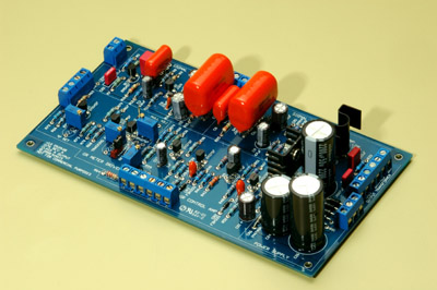
To elaborate, I did the Q Bias adjustment already, of course, and had no problems there. As far as the zero adjust, I have the unit set appropriately, and can zero the VU with R71, but I can't get reach 0v with R75. I have the latest version of the board, R71 is panel mounted with the appropriate 2k pot, and the trimmers on the board are oriented exactly as they appear here:

1176_rev_a_stuffed_small.jpg


I'm measuring at TP10 and 11, and the jumper is oriented to connect the two pins closest to the front panel. During the Q Bias adjustment, it was oriented the other way.

Is it the case that some people were only able to complete this step by choosing a different value for R71 or R75? I was pretty meticulous in putting together the unit, so I'm confident the appropriate values are in the right places, and the connections should be pretty solid. I let the unit warm up for over 20 minutes before starting this step and it spent last night burning in without issue. Is it normal for R75 to spin infinitely? This might make me think that it is broken, except for the fact that it does appear to adjust voltage between a certain range of turns. I'll continue to browse this thread, but any tips from anyone who had issues with this step would be greatly appreciated. It sucks to be this close to having a fully functioning compressor and hit a snag  :-[
 
Back
Top