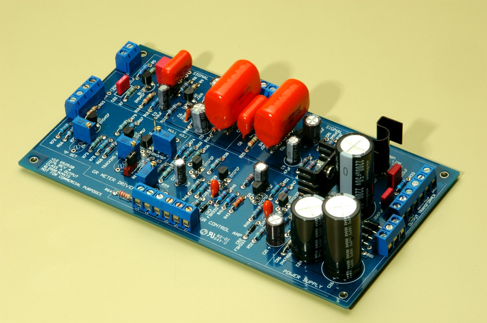
[BUILD] 1176 Rev A - Back to the beginning...

GroupDIY Audio Forum

Help Support GroupDIY Audio Forum:

This site may earn a commission from merchant affiliate links, including eBay, Amazon, and others.
Also wanted to add that I tested all components before installing and they all checked out. Again, I took it very slow and am pretty certain all values are in the correct places. Voltage rails test fine.

I am getting as low as .75v to 1v, but it seems the needle is at one extreme or the other at this level. I can increase the voltage by a fair bit easily while adjusting, but can't get below around .75v. Seen a few mentions of changing the 2k null adjust pot out for a 5k. Is that recommended without any unwanted issues resulting?
 
Does anybody have problems with Rev A oscillating if the output pot is set close to maximum? Mine goes crazy and stops only when I touch the "7" point. Looks like a sidechain thing... Anybody?
 
Does anybody have problems with Rev A oscillating if the output pot is set close to maximum? Mine goes crazy and stops only when I touch the "7" point. Looks like a sidechain thing... Anybody?

I had this problem and it took me forever to figure out what was going on. I finally installed the ground wire from the pcb ground to the chassis start point, and the oscillations stopped immediately!
Also check the shielding for the wires to the output pot.
If you pull the FETs you will be able to tell if it is the sidechain.
 
dmp said:
I had this problem and it took me forever to figure out what was going on. I finally installed the ground wire from the pcb ground to the chassis start point, and the oscillations stopped immediately!
Also check the shielding for the wires to the output pot.
If you pull the FETs you will be able to tell if it is the sidechain.

Thanks, I'll try this. I have the wire from the PSU cap to chassis though. I'll see if the wire from CT of power trafo will stop the oscillation.
The shields are fine. I'll check with FETs out as you suggest as well.
 
Update on my calibration issue - I tried a 5k trimmer for R75 - no effect on calibration. 2k trimmer is back in now.

Checked continuity on the meter board as well as the meter driver section of the main PCB. All checks out, including continuity between these boards, and between R71 and the main PCB. Haven't found continuity between points that shouldn't be connected.

All resistor values check out as well, except for a few (R66, R73, R76 and R79) which didn't read right in circuit, but tested fine out of circuit. Q12 and Q13 pretty closely matched, jumper still set appropriately per my earlier post, trimmers still oriented properly per my earlier post and R71/R75 values check out (I think, at least - R75 ranges from 2Ω-1.92kΩ, R71 ranges from near 0 to 1.65kΩ). I can see how these values may be causing an issue, but they are in circuit and I believe they tested ok last time I checked out of circuit.

What else could it be? I feel like I've checked everything! I touched up all joints in the meter driver section. I suppose something could still not be right there, but my work there and throughout the board was pretty clean - nothing looks off and the unit otherwise seems happy and is passing signal cleanly. I contacted Mako, but received no reply.

Please help - what haven't I checked? What should I be looking at? Are R71/R75 suspect based on the information above? If so, I assume it would be R71 considering the change I made to R75 with no effect on the calibration? I can adjust the meter with R71/R75, just can't zero out the test points. :(
 
ALL the trimmers have to be in some reasonable range or it won't calibrate. Try turning some other ones. Not the Qbias obviously tho. If all is well you will get 0 volts. But set your Dimm range to the suggested settings in the video. Not to millivolts or something. I think it was a 1 10th volt range?

And connect your Dimm to the 2 test points on the board. TP1 and TP2? I believe? There has been some confusion over that cause on the rev D you measure across a resistor. On the rev A you use the 2 test points instead.

And I know someone has broken A trim pot by turning it too far once but I have found that not to be the case for me anyway. I have turned those pots A million times past the click with no problems. Maybe not A million...

If you were very careful assembling then maybe one of the other trimmers is out of range. When in doubt start twisting knobs. (Or trimmers in this case)

John
 
steve_h I had already mentioned in my email reply, but be sure you are measuring DC volts at test points TP10 and TP11 with no audio passing through the unit.  (not sure if audio passing will have impact but it's not needed for this step)  .75V-1V seems very high, anyone else think so?  Verify your DMM is working properly in DC range on a AA or other 1.5V battery.  Not sure what else to suggest so hopefully someone will chime with a bit more knowledge.
 
Ok. Here's an update.
I've tried grounding CT of the transformer - no effect on oscillation. Without both (or any) of FETs the unit still oscillates. With the pads of the output pot shorted (= max. output gain) the unit oscillates.
I still can't find the source of oscillation. I'm now starting to suspect the output amp... Any thoughts?
 
Have you heat-sink'd your LM317/337?

What happens to +30V rail when oscillation is present?

I had oscillation issues that turned out to be related to thermal shutdown of the LM317 and a piece of aluminum heat-sink bolted to the 317 resolved the issue.

Thx,
jb

 
0dbfs said:
Have you heat-sink'd your LM317/337?

What happens to +30V rail when oscillation is present?

Yes, the heatsink is in place. Both rails don't change when oscillation kicks in. This is not a power related problem for sure. I think that maybe there're some traces that are too long...
 
Hi everyone,

Finally completed my first of two Rev A units, and it now appears to be working correctly.
There was this wierd low-end oscilation that was present when the output was connected to my patch bay (but not directly back to the desk). It seemed to disappear all of a sudden, and used to stop when the output cable was unplugged. The meter used to go up to full and the horrid noise came out of the unit.
Anyway, it seems to have magically disappeared (yes, i had calibrated it prior to this issue coming and going), and it is very very quiet.
All function seems to work correctly other than ratio 4:1 seems to do nothing at all - no GR at all. I'll look into that one later.

Ok, onto unit no. 2 then...

Anthony.
 
Ok, so the zero adjust issue is resolved - thanks for the suggestions :) The meter was metering DC volts - the issue was related to the orientation of the Q Bias trimmer.

Stuck with a new issue now, which is that I can't complete the gain reduction meter tracking adjustment as the unit does not want to compress at all. Again, it passes audio just fine - what comes out sounds just like what goes in, including when compression is enabled by disengaging bypass via the attack knob. Engaging compression doesn't affect the sound any differently than bypass and the needle barely moves, if at all. I'm confident that the Q Bias adjustment was successful. I've checked continuity extensively within and between all relevant points on the ratio board, attack/release pots, and 19-22 + ground on the front of the board. The attack knob does appear to short to ground when disengaged as expected, and not when engaged. Didn't come across any instances of continuity that didn't make sense.

I have searched this thread and the Rev D thread for similar issues and in cases where a solution was reached, the same solution was not effective in this case. I even went so far as to message a member who had this issue earlier in the thread where no apparent resolution was reached to see if he figured it out, but he did not. Again, I was methodical about putting this together and while I will check everything related to the ratio board and attack/release knobs, I doubt that something is connected improperly there.

A few additional questions - is it normal for adjustment of the release knob to affect the meter when metering gain reduction? It seems mine moves the needle higher when turning the release counter clockwise and lower when moving clockwise, over a range of about 1 db. No audio being fed into the unit and it happens regardless of compression enabled/disabled. Not an issue with +4/+8 metering modes.

Perhaps this is related to the issue described above, or maybe it's normal - could someone let me know? Again, I searched and found nothing related to this topic.

Lastly, has anyone else found that R71 needs to be turned up all the way to allow the meter to reach 0 or close to 0 when metering gain reduction?

One final bit of information is that my tracking adjustment trimmer is set to be fully counter clockwise as I'm assuming is the correct orientation prior to calibrating tracking adjustment. Before someone chimes in to say this information is not useful as the orientation of the trimmer is not known - my tracking adjustment trimmer is oriented exactly the same as the mnats PCB image I posted earlier. Per the above, I haven't reached the tracking adjustment step yet but I understand the trimmer affects the meter and may be a factor in some of the above issues.
 
I believe you soldered your bias adjust trimmer the wrong angle and thus shorted all its pads. Otherwise its orientation doesn't matter - it would just work backwards if installed incorrectly.

Now, you may check the resistance between pad 7 and ground. Even 10M resistance there will shut the sidechain down.

You obviously have some problems. And your trimmers aren't supposed to sit at the end of their rotation range. Check and double check for incorrect parts and solder bridges.

Release knob does move a meter in gr mode a bit. At least on my unit.
 
Thanks for the reply :)

To reiterate, my trimmers are all oriented exactly as they appear in this picture:

1176_rev_a_med.jpg


All trimmers do appear to function properly and all have shown movement on the meter. The only difference between the picture and my board is that in my case, R71 is not a trimmer on the board, but a pot mounted to the chassis per the wiring guide, configured the same way as the instructions indicate.

Just checked resistance with the unit off between pad 7 and ground - got 258.5k regardless of where the attack knob was.

Where should the tracking adjust trimmer be sitting prior to the last calibration step?
 
In serious need of advice/suggestions here..

I've re-checked all relevant connections, tested continuity on the ratio board, and restarted the calibration process from the beginning to no avail - all checks out and appears normal except for the lack of compression. Checked wiring against the wiring guide and it matched. Touched up some connections around the ratio board and attack/release pots. No issues or weirdness with the Q Bias adjustment step, so it does appear the FET going into conduction as needed. Definitely giving the unit suffient time to warm up before doing anything.

Some additional details - when engaging compression via the attack knob at 20:1, I get a voltage drop of between .003 and .004v AC measured at output xlr (legs 2 and 3). Increasing the output or input results in an increase in voltage. I should be seeing a decrease, correct? The meter very slightly moves when compression is engaged in GR mode, but doesn't otherwise seem to react to any change to input/output - just sits still at 0.

So what could be wrong here? What is the likely culprit, based on the above? Connection issue between two points? Cold solder joint on the board/bridged connection? Something grounding out? Ratio board? Attack/release configuration? Transistor? Is there a specific section on the main PCB that the issue likely relates to? Please be as specific as possible.

Is my resistance reading between pad 7 and ground per my last post ok? Where should the tracking adjust trimmer be sitting prior to the last calibration step?

To be clear, I'm stuck on the last step of calibration - the first 2 steps were issue free. Adjusting the level going into the unit doesn't appear to have any effect - just wanted to mention this as I know some people had better success with 1.223v vs .775v for step 3.

Please help  :-[
 
Ok, here are a few pictures of the other side of the front panel as well as the GR Meter Driver section of the main PCB (click on the images to zoom in):

http://imageshack.us/photo/my-images/807/56078075.jpg/
http://imageshack.us/photo/my-images/7/76952956.jpg/
http://imageshack.us/photo/my-images/36/28735875.jpg/
 
Back
Top